
Novel methodology to realize automatic virtual metrology

An automated, measurement technology for electrical components, comprehensive factory control, semiconductor/solid-state device manufacturing, etc., that solves problems such as missing parameters or steps, inaccuracies, mispredictions, etc.

Active Publication Date: 2009-11-18
TAIWAN SEMICON MFG CO LTD
View PDF0 Cites 10 Cited by
  • Summary
  • Abstract
  • Description
  • Claims
  • Application Information

AI Technical Summary

Problems solved by technology

However, the existing virtual measurement model requires a lot of manpower to analyze and confirm each parameter and step, which is very time-consuming
In addition, some key parameters or steps may be missed due to wrong judgments, resulting in inaccurate and wrong predictions
Related wafer variances cannot be predicted with existing methods and existing virtual metrology models

Method used


Image

  • Novel methodology to realize automatic virtual metrology
  • Novel methodology to realize automatic virtual metrology
  • Novel methodology to realize automatic virtual metrology

Examples


Embodiment Construction

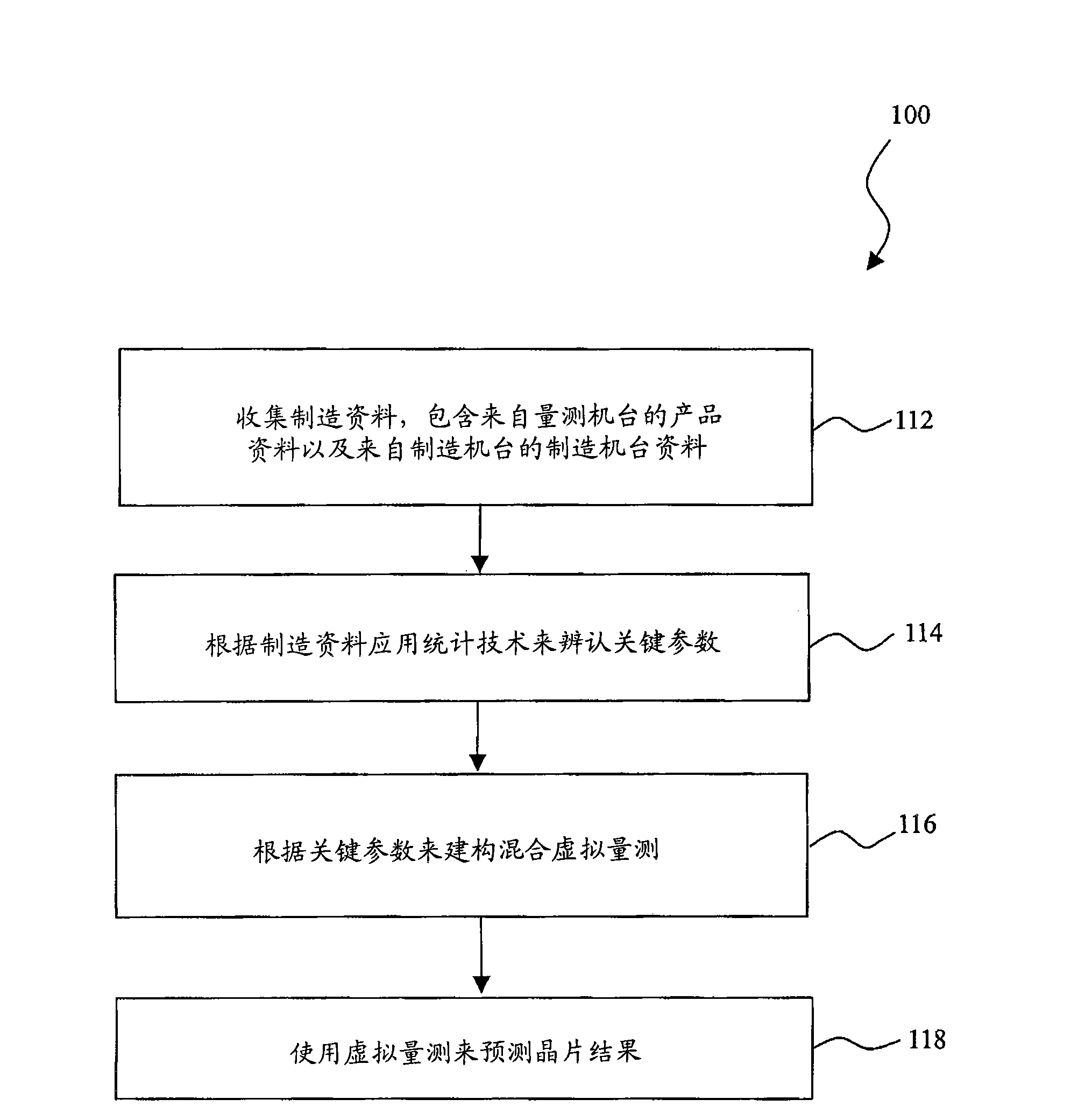
[0041] It is to be understood that the present invention provides many different embodiments or examples for implementing the various features of the present invention. Specific equipment and configurations are described below to simplify the present invention. These are of course examples only and not intended to be limiting. Furthermore, the present disclosure may repeat reference numerals and / or text in different instances. The repetition is for the purpose of simplicity and clarity and does not represent a relationship between the different embodiments or configurations discussed. The present invention provides an innovative approach to enable wafer outcome prediction across batch fabrication tools. Various examples, embodiments, variations, and varieties of the invention are described below.

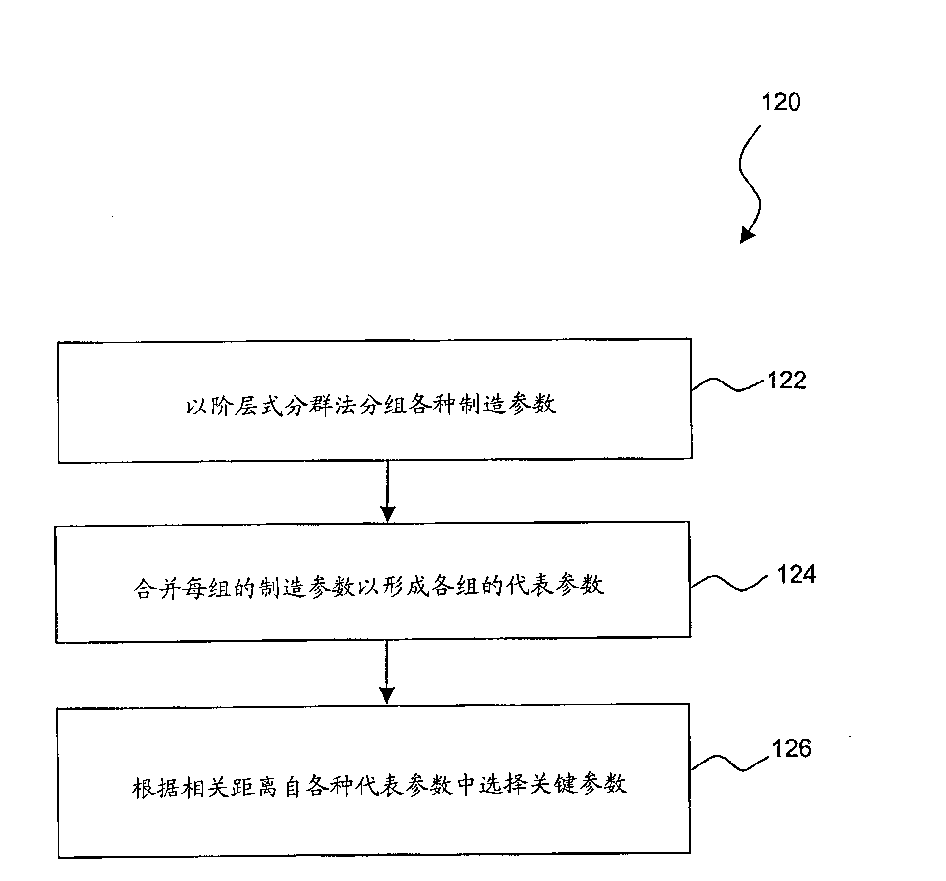
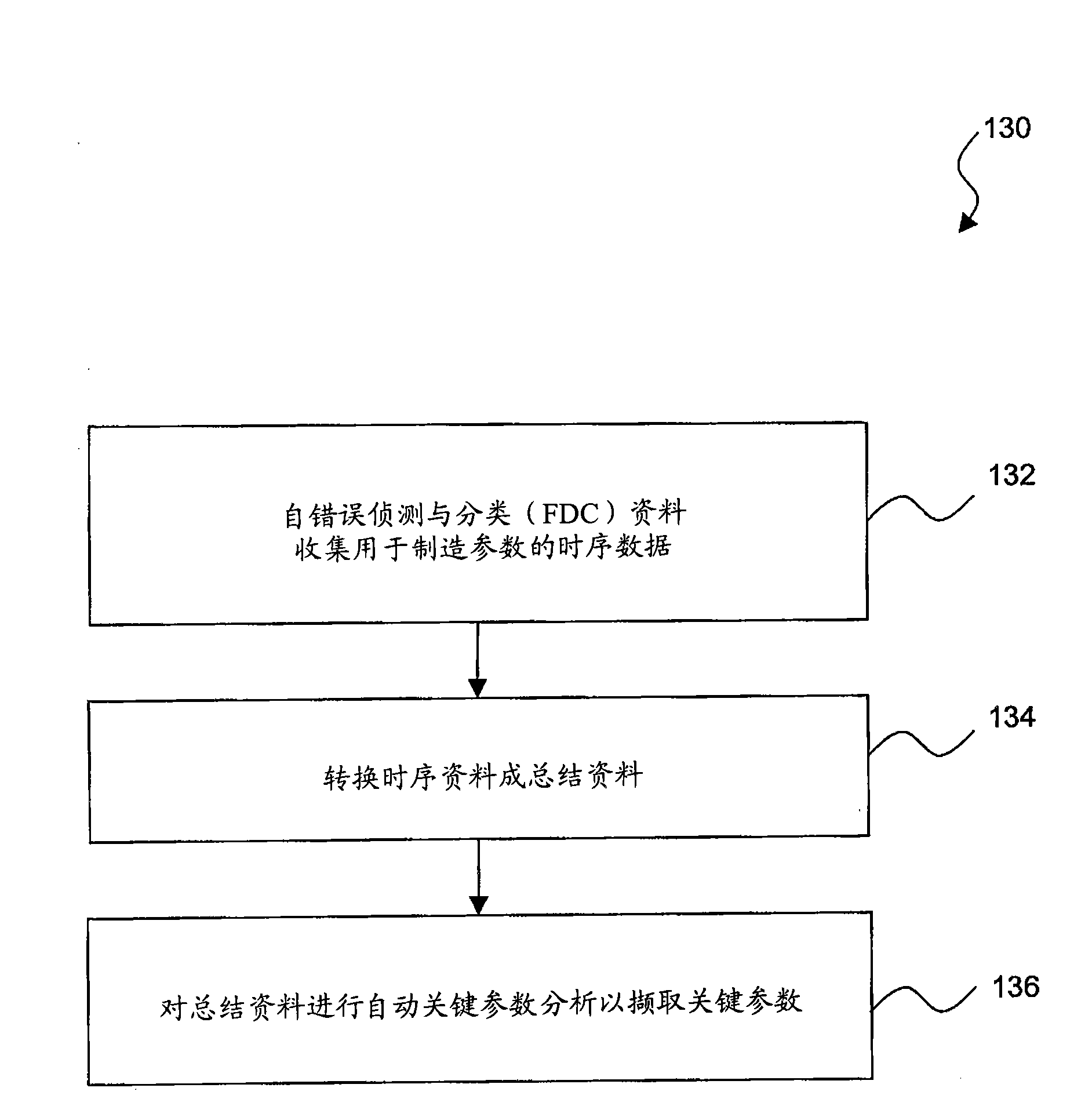
[0042] figure 1 A simplified flow diagram of a method 100 for enabling wafer result prediction using hybrid virtual metrology and / or clustering techniques. Image 6 It is a blo...


PUM


Abstract

The invention provides a method to enable wafer result prediction includes collecting manufacturing data from various semiconductor manufacturing tools and metrology tools; choosing key parameters using an autokey method based on the manufacturing data; building a virtual metrology based on the key parameters; and predicting wafer results using the virtual metrology.

Description

technical field [0001] The present invention relates to an automatic virtual measurement method, in particular to an automatic virtual measurement method capable of realizing wafer result prediction. Background technique [0002] Semiconductor integrated circuit wafers are produced in a fab facility through a number of processes. These processes and associated fabrication tools may include thermal oxidation, diffusion, ion implantation, rapid thermal processing (RTP), chemical vapor deposition (CVD), physical vapor deposition (PVD), epitaxy, etching, and lithography. Measurement tools are used to monitor and control products (eg, semiconductor wafers) during the manufacturing stage for quality and yield. As the critical dimensions of integrated circuits decrease, it may become necessary to increase the amount of monitoring and control. However, this increases costs because of the increased number of measurement machines, the increased manpower required for monitoring and c...

Claims


Application Information

Patent Timeline
Patent Type & Authority Applications(China)
IPC IPC(8): G05B19/418H01L21/00
Inventor 汪青蓉林俊贤赖志维柯俊成罗冠腾左克伟陈炳旭余振华
Owner TAIWAN SEMICON MFG CO LTD
Learn More