
Electromagnetic short current protective mechanism for breaker

A short-circuit protection and circuit breaker technology, applied in the protection switch operation/release mechanism, protection against overcurrent, etc., can solve problems such as being unfavorable to reduce short-circuit faults, difficult to ensure operational safety, and inability to shorten time, etc. Improve work reliability and stability, shorten tripping time, and ensure the effect of internal insulation level

Active Publication Date: 2009-11-18
CHANGSHU SWITCHGEAR MFG CO LTD (FORMER CHANGSHU SWITCHGEAR PLANT)
View PDF1 Cites 7 Cited by
  • Summary
  • Abstract
  • Description
  • Claims
  • Application Information

AI Technical Summary

Problems solved by technology

It is precisely because of the indirect actuation mode of the transition of the ejector rod that the armature moves to the ejector rod, and the time for the ejector rod to push the lock of the circuit breaker operating mechanism cannot be shortened, resulting in the following problems: On the one hand, the circuit breaker disconnects the fault circuit Low reliability and poor stability; on the other hand, it is not conducive to reducing the impact of short-circuit faults on personal safety, lines and power equipment
In addition, the structure of the technical solution of CN101373688A is relatively bloated, and the configuration of such a structure will be limited when the housing space of the circuit breaker is limited, for example
In addition, when the upper cover of the circuit breaker is opened for maintenance or replacement of internal accessories, since the first bracket and the yoke are metal conductors, they are easily charged and exposed outside, making it difficult to guarantee operational safety, and the internal insulation level poor

Method used


Image

  • Electromagnetic short current protective mechanism for breaker
  • Electromagnetic short current protective mechanism for breaker

Examples


Embodiment Construction

[0019] In order to enable the examiners of the patent office and the public to understand the technical essence and beneficial effects of the present invention more clearly, the applicant will describe in detail below in conjunction with the accompanying drawings in the form of embodiments, but none of the descriptions of the embodiments is a description of the present invention. Restriction of the scheme, any equivalent transformation made according to the concept of the present invention which is only in form but not in substance shall be regarded as the scope of the technical scheme of the present invention.

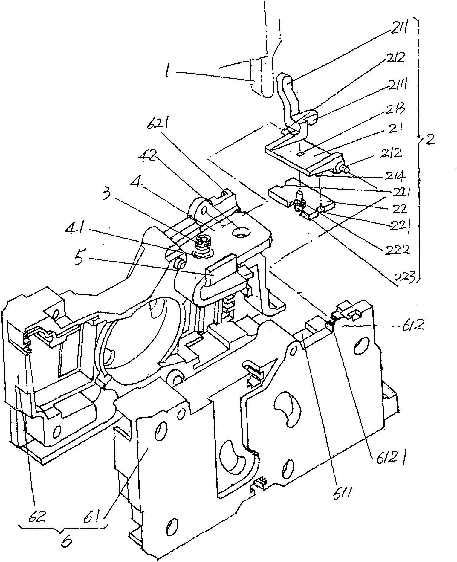
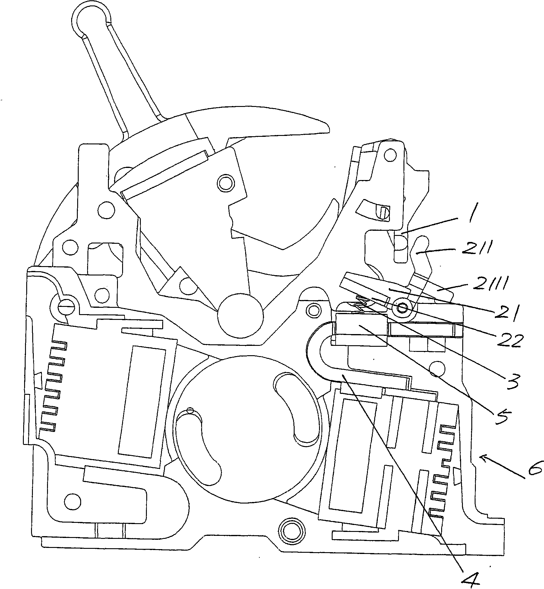
[0020] please see figure 1 The arc extinguishing chamber casing 6 of the circuit breaker is composed of the first and second shell flaps 61 and 62 facing each other and merging (clapping) each other. The arc grid sheet and the movable contact bridge as the movable contact and a pair of static contacts (upper and lower static contacts), the movable contact bridge and t...


PUM


Abstract

An electromagnetic short current protective mechanism for a breaker belongs to the technical field of low voltage electric appliances. The protective mechanism is characterized by comprising an iron core, an elastic element and a lock catch actuating device, wherein the iron core is used for being arranged on the upper part of one end along the length direction of an arc extinguish chamber shell of the breaker and is matched with an upper fixed contact arranged on the arc extinguish chamber shell; the elastic element is supported on the upper fixed contact; and the lock catch actuating device of a lock catch is used for actuating a breaker operating mechanism, and the lock catch actuating device is hinged on the arc extinguish chamber shell and is contacted with the elastic element. The protective mechanism has the advantages of having concise structure, saving space usage, improving operational reliability and stability of the breaker and ensuring personal safety and the safety of circuits and power equipment. Meanwhile, the protective mechanism guarantees the internal isolation level and has good processing safety particularly when a roof cover of the breaker is opened to perform maintenance or replace internal attachments.

Description

technical field [0001] The invention belongs to the technical field of low-voltage electrical appliances, and in particular relates to an electromagnetic short-circuit protection mechanism of a circuit breaker, which is used for actuating the lock of the operating mechanism of the circuit breaker to trip the circuit breaker. Background technique [0002] Circuit breakers are suitable for low-voltage power distribution networks to distribute electric energy and protect circuits. Circuit breakers have overload, short circuit and undervoltage protection functions to avoid damage to circuits and power supply equipment. Among them, the short-circuit protection mechanism is an extremely important mechanism in the circuit breaker, because the operating time of the short-circuit protection mechanism will directly affect the breaking capacity of the circuit breaker. [0003] In the existing rotary double-breakpoint circuit breaker, the structure of the rear-stage short-circuit protec...

Claims


Application Information

Patent Timeline
Patent Type & Authority Applications(China)
IPC IPC(8): H01H71/24H02H3/08
Inventor 张洵初陈志刚王炯华管瑞良
Owner CHANGSHU SWITCHGEAR MFG CO LTD (FORMER CHANGSHU SWITCHGEAR PLANT)
Learn More