Communicated method, communication system and communication routing device based on SPI bus

A technology of SPI bus and communication method, applied in the direction of data exchange, transmission system, bus network, etc. through path configuration, can solve the problems of revision of printed circuit board, large number of pins, and occupation of pin resources on the host side of the system, etc. Achieve the effect of saving the number of pins and facilitating expansion

Active Publication Date: 2009-11-18
SHENZHEN MINDRAY BIO MEDICAL ELECTRONICS CO LTD +1
View PDF0 Cites 26 Cited by
  • Summary
  • Abstract
  • Description
  • Claims
  • Application Information

AI Technical Summary

Problems solved by technology

[0004] Among the above schemes, the disadvantages of scheme 1 and scheme 2 are obvious. Since there are many communication pins between the host and multiple probes, a large amount of pin resources on the host side of the system are occupied. If you add probes during the upgrade, you need to add more pins. lead to the revision of t

Method used


Image

  • Communicated method, communication system and communication routing device based on SPI bus
  • Communicated method, communication system and communication routing device based on SPI bus
  • Communicated method, communication system and communication routing device based on SPI bus

Examples


Embodiment Construction

[0048] The features and advantages of the present invention will be described in detail with reference to the accompanying drawings.

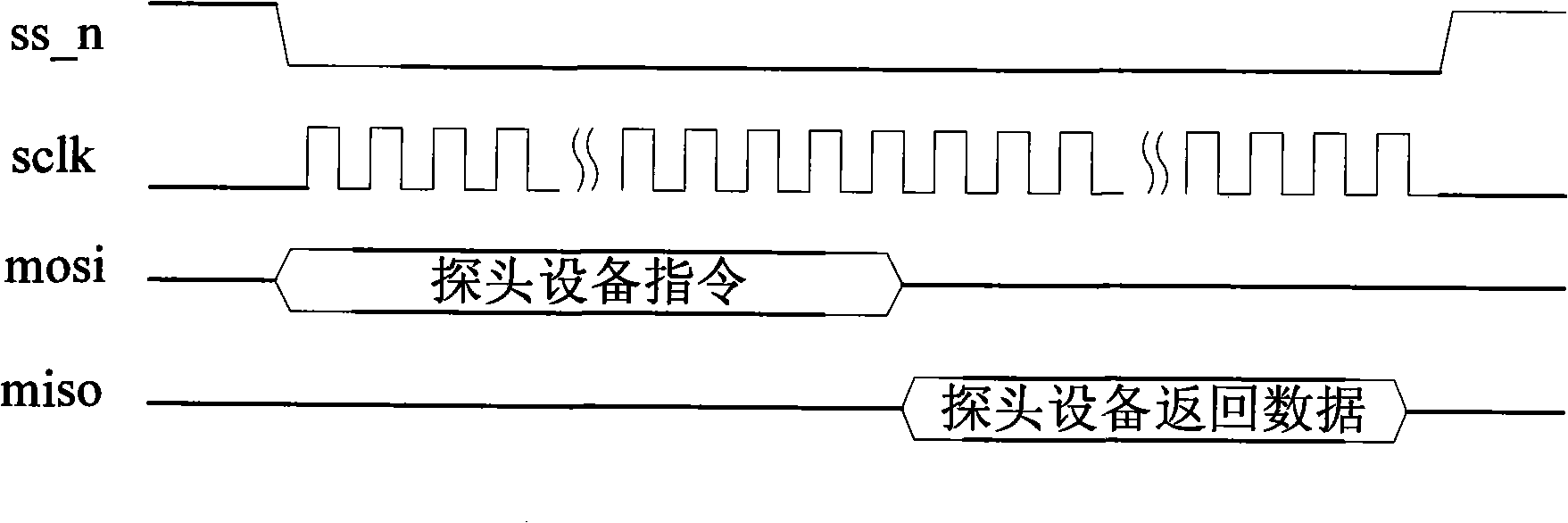
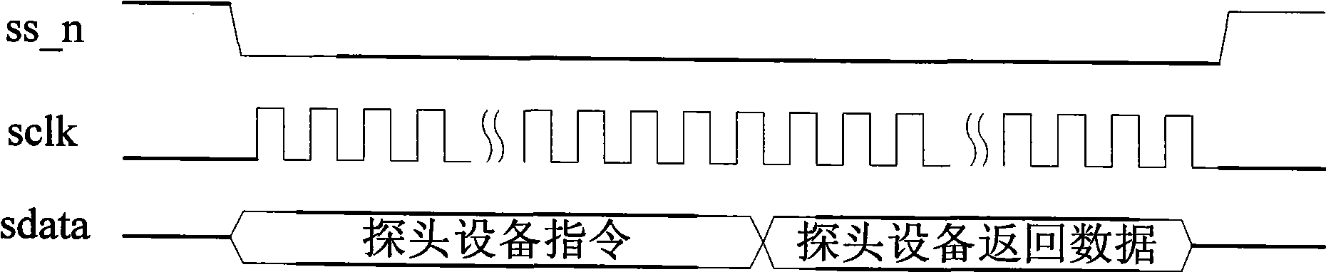
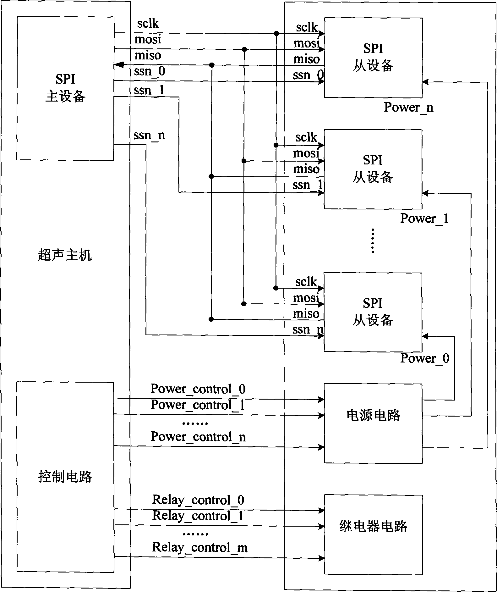
[0049] Please refer to Figure 6 A communication system based on the SPI bus includes a SPI master device 110, a plurality (n) of SPI slave devices 201 and a plurality of electrical units, and each electrical unit is located in the power supply circuit 202 and the relay circuit 203. The power supply circuit 202 has a power supply interface for supplying power to each SPI slave device 201, the relay circuit 203 includes a plurality of relays, the power switch on each power supply interface and each relay is an electrical unit in the communication system. It also includes a communication routing device 215. The SPI master device 110 communicates with the communication through the 4-wire SPI bus—chip select signal line m_ss_n, serial clock signal line m_sclk, master-out slave-in data line m_mosi, and master-in slave-out data line m_miso The input...


PUM


Abstract

The invention discloses a communication method based on an SPI bus, comprising the following steps: providing selection signals of slave equipment through a data line of main equipment; determining the selected slave equipment according to the selection signals; carrying out accessing operation on the selected slave equipment through the main equipment; providing selection signals of a controlled electric unit through the data line of the main equipment; selecting the controlled electric unit according to the selection signals, and generating an open/close control command of the controlled electric unit; sending the control command to the controlled electric unit to control actions of the controlled electric unit. The invention also discloses a communication system based the on the SPI bus and a communication routing device used for the communication system. SPI main equipment provides the selection signals through the data line, and determines a selected operation object according to treatment of the signals, therefore, the accessing operation of the main equipment on the slave equipment can be realized only needing the SPI bus of 3 line or 4 line and without arranging more pins on a host end to descend any other control signals.

Description

【Technical field】 [0001] The present invention relates to SPI (serial peripheral interface, serial peripheral interface) bus control, in particular to a communication method and communication system based on the SPI bus. 【Background technique】 [0002] The SPI bus system is a synchronous serial peripheral interface, which is a commonly used industrial standard bus, through which the host computer and various peripheral devices can exchange information in a serial manner. For example, ultrasonic diagnostic systems in the medical field are generally equipped with multiple probes. In order to identify the probes, each probe can be equipped with a non-volatile memory or logic device for storing information such as the ID code of the probe. These storage devices are used as slave devices. The host computer of the ultrasonic diagnostic system can be accessed through the SPI bus to obtain the ID code, and the control of the host computer on the power supply and relays on the system...

Claims


Application Information

Patent Timeline
IPC IPC(8): H04L12/40H04L29/02
Inventor 程东彪张立国宋炜华康小刚
Owner SHENZHEN MINDRAY BIO MEDICAL ELECTRONICS CO LTD
Why Eureka
Try Eureka