Fixing device combination

A technology for fixing devices and installation grooves, which is applied in the direction of elastic/clamping devices, electric solid devices, circuit layout on support structures, etc., and can solve the problems of increasing material costs and assembly costs, buckle buckles not tight, installation buckles, etc. It eliminates the risk of circuit board short circuit, reduces the cost of materials, and reduces the cost of assembly

Inactive Publication Date: 2009-11-18
FU ZHUN PRECISION IND SHENZHEN +1
View PDF0 Cites 3 Cited by
  • Summary
  • Abstract
  • Description
  • Claims
  • Application Information

AI Technical Summary

Problems solved by technology

However, after the heat sink is installed on the circuit board, the retaining ring has no function, and the installation of the retaining ring is also time-consuming, which increases the material cost and assembly cost, and may cause the retaining ring to be damaged due to improper assembly. The buckle is not tight, especially when the buckle is made of metal, it will cause the risk of circuit board short circuit after it falls off

Method used


Image

  • Fixing device combination
  • Fixing device combination
  • Fixing device combination

Examples


Embodiment Construction

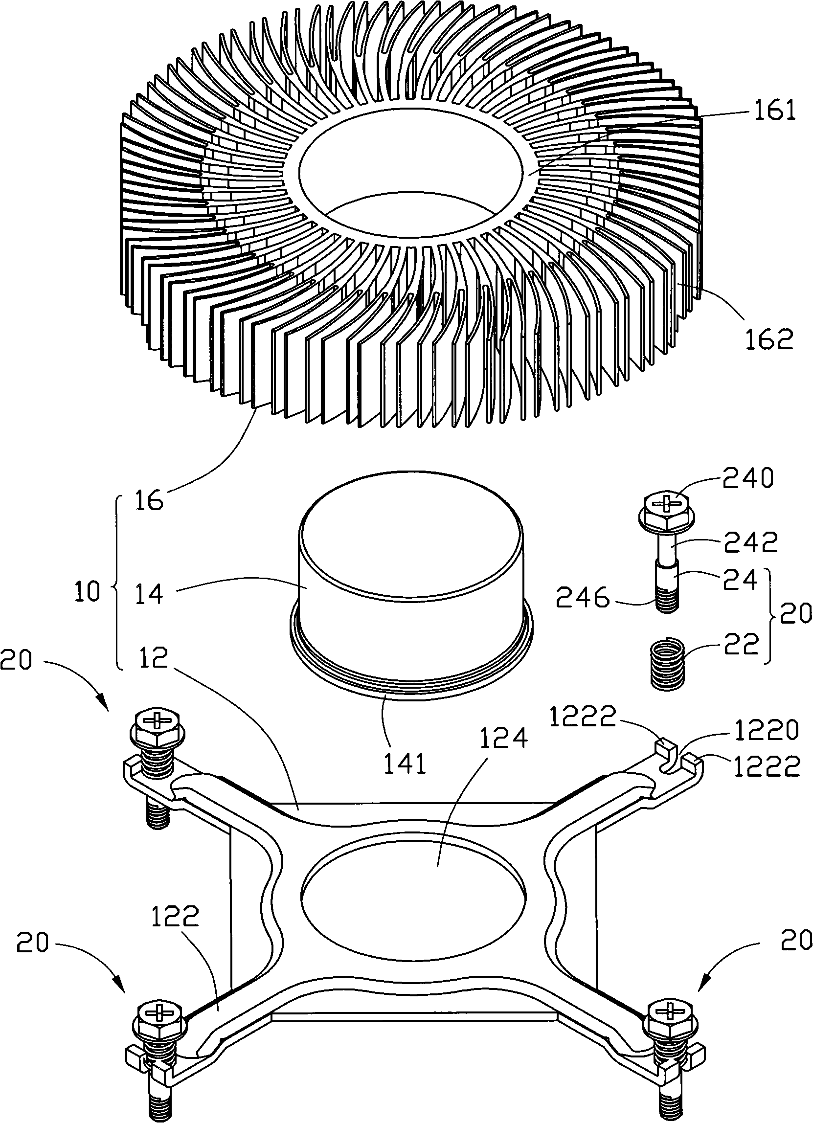
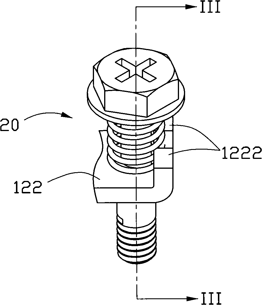
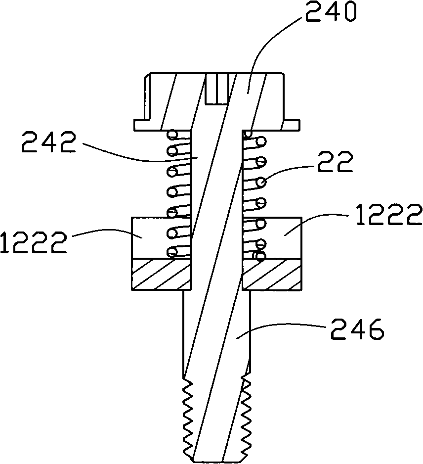
[0014] see Figure 1 to Figure 3 , the fixing device combination includes a heat sink 10 and several spring fasteners 20 .

[0015] The heat sink 10 includes a substrate 12 , a heat transfer column 14 and a heat sink 16 . The base plate 12 is square, with a through hole 124 formed in the center thereof, and a buckle ear 122 extending outward from four corners of the base plate 12 . The base plate 12 is integrally stamped from sheet metal parts, so the manufacturing process is simple and the production efficiency is high. The heat transfer cylinder 14 is cylindrical, and the bottom thereof protrudes outward to form a protruding ring 141 . The outer diameter of the protruding ring 141 is larger than the diameter of the through hole 124 . In this embodiment, the heat transfer cylinder 14 is a solid cylinder, such as a copper cylinder. The radiator 16 includes a hollow circular cylinder 161 in the middle and a plurality of cooling fins 162 disposed around the cylinder 161 . Th...


PUM


Abstract

The invention relates to a fixing device combination, comprising a substrate and at least one spring fastener. Each spring fastener comprises a body and a spring sleeved on the body; a pressing portion is formed at one end of the body; a buckling portion is formed at the other end of the body opposite to the pressing portion, the body further comprises a slender rod portion between the pressing portion and the buckling portion; the substrate is provided with at least one mounting groove communicating with the substrate, an opening is formed at the outer side of the mounting groove; the width of the mounting groove is less than the outer diameter of the buckling portion but is not less than the outer diameter of the slender rod portion; the slender rod portion is clamped in the mounting groove from the opening; the buckling portion is located below the mounting groove and supports against the lower side of the mounting groove; at least one stopping portion is formed in the position where the substrate is adjacent to the mounting groove and supports against the spring fastener to prevent the spring fastener from dropping from the opening of the mounting groove.

Description

technical field [0001] The invention relates to a fixing device combination, in particular to a heat dissipation device combination which uses fixing fasteners to fix a radiator to a heating electronic component. Background technique [0002] With the rapid development of the computer industry, more and more heat is generated by heat-generating electronic components such as micro-processing chips. The electronic components dissipate heat, and the heat sink is usually fixed on the circuit board where the electronic components are located by fixing fasteners such as spring screws. The existing method is to provide a number of through holes on the heat sink, and the diameter of the through holes is larger than the diameter of the thread And smaller than the outer diameter of the spring, so the thread can pass through the through hole and be connected with the corresponding threaded hole on the circuit board. In order to facilitate transportation, often after the spring screw a...

Claims


Application Information

Patent Timeline
Patent Type & Authority Applications(China)
IPC IPC(8): H05K7/12H05K7/20H01L23/34H01L23/40G06F1/20
CPCH01L23/467H01L23/4006H01L2924/0002H01L2924/00
Inventor 查新祥
Owner FU ZHUN PRECISION IND SHENZHEN
Why Eureka
Try Eureka