Al technical title is built by PatSnap Al team. It summarizes the technical point description of the patent document.
A filler, spherical technology, used in fire rescue and other directions, can solve the problems of not gaining market penetration, not suitable for preventing flames from extinguishing, etc.
Inactive Publication Date: 2014-04-30
托马斯·K·斯特尔泽尔
View PDF8 Cites 2 Cited by
Summary
Abstract
Description
Claims
Application Information
AI Technical Summary
This helps you quickly interpret patents by identifying the three key elements:
Problems solved by technology
Method used
Benefits of technology
Problems solved by technology
These insecurities for users and customers lead to the fact that although this concept exists in the market thirty years from now, the presently described filling bodies made of metal mesh panels do not achieve wide market penetration
As serious disadvantages of packing bodies produced from metal mesh according to the mentioned method, the case is also mentioned in particular that this packing body is clearly deficient with regard to its ability to flow through liquids and gases, and practically Significant flow resistance on
In general, and also an important disadvantage of the whole method, the insertion of a metal mesh sheet with the shape of a reticulated ball and a filling body made of metal mesh sheets, makes this applied physical principle of surface enlargement or flame cooling suitable only for protection against explosions , but not suitable for preventing flames or for extinguishing flames
Method used
Image
Click on the blue label to locate the original text in one second.
Reading with bidirectional positioning of images and text.
Examples
Embodiment Construction
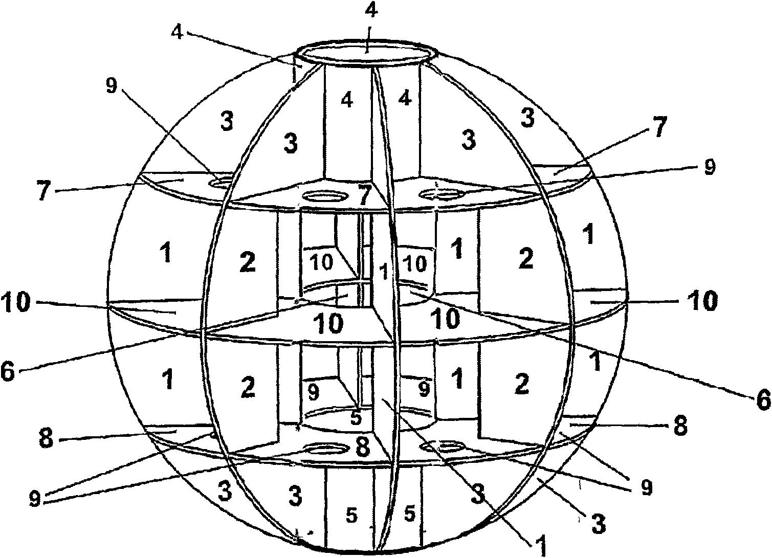
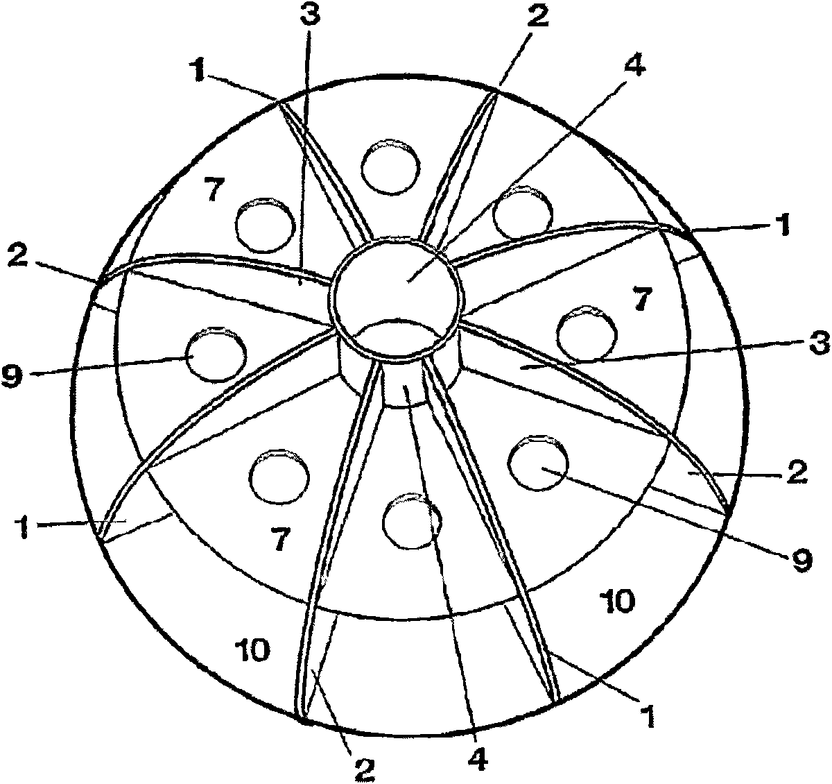
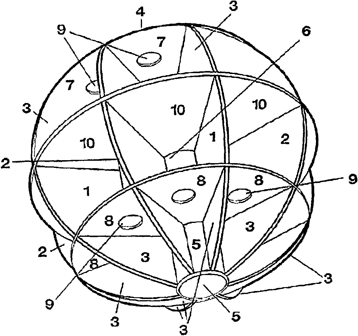
[0045] figure 1 , figure 2 and image 3 A spherical packing body according to the invention is shown, which is formed from a plurality of disc-shaped circular vertical planes 1 , 2 and 3 and disc-shaped circular horizontal planes 7 , 8 and 10 extending parallel to each other. Circular opening 6 is positioned at the center of horizontal plane 10, and described circular opening 6 is formed in the center together with the circular sleeve-shaped body 4 of upward inward opening and the circular sleeve-shaped body 5 of downward inward opening from upper sleeve-shaped body 4 to the axial through-pipe of the lower sleeve-shaped body 5, wherein the inner diameters of the sleeve-shaped and inwardly open circular bodies 4 and 5 and the circular opening 6 are the same. From the outer edge of the spherical body a vertical plane 1 extends to the edge of each circular opening 4 , 5 and 6 and to the edge of a horizontal plane 7 , 10 and 8 respectively extending around said opening in para...
PUM
Abstract
The invention relates to the production of a spherical hollow filling body for filling containers for combustible and inflammable liquids or gases, and to a method for the especially advantageous usesthereof, for example, for preventing explosive combustion processes and explosions, for extinguishing fires, as protection against corrosion in tanks, for separating fuels and water, as protection ag ainst bacteria and fungi in fuel tanks, as protection against theft, for reducing hydrocarbon emissions, for increasing the stability and safety of tanks in the event of a crash, for reducing the boil-off effect of hydrogen, for applications in the chemical industry, for deriving static electricity from fuel containers, for protection against electromagnetic interferences, for reducing and slowingdown the B.L.E.V.E. effect, for increasing the filling quantity of gas containers, for heating and cooling liquids and gases, and for reducing evaporation loss. The invention also relates to methodsfor producing the filling body. Figure 1 shows a spherical filling body according to the invention, consisting of a plurality of disk-type circular vertical surfaces (1, 2 and 3) and a plurality of disk-type circular horizontal surfaces (7, 8 and 10) which are parallel to each other. A circular opening (6) is located in the centre of the horizontal surface (10), said opening forming an axial continuous tube in the centre, from the top (4) to the bottom (5), together with the upper, inwardly open, circular sleeve-type body (4) and the lower, inwardly open, circular sleeve-type body (5), the inner diameters of the sleeve-type, inwardly open circular bodies (4 and 5) and the circular opening (6) being identical. The vertical surfaces (1) extend from the outer edge of the spherical body to theedge of each circular opening (4, 5 and 6) of the parallel horizontal surfaces (7, 10 and 8) respectively surrounding the openings.
Description
technical field [0001] The invention relates to an object having the shape of a spherical hollow filling body for filling containers for combustible and ignitable liquids or gases, and to a particularly advantageous method of use of said object, for example for Protection against explosive combustion processes and explosions, for extinguishing flames, as protection against corrosion in tank containers, for separating fuel and water, as protection against bacteria and fungi in fuel tanks, as protection against theft, for reducing hydrocarbons Emissions, for increasing the stability and crash safety of tank containers, for reducing the "evaporation effect" of hydrogen, for use in the chemical industry, for conducting static electricity away from fuel containers, for protection against electromagnetic interference , for reducing and delaying boiling liquid expansion vapor explosion effects, for increasing the filling capacity of gas containers, for heating and cooling liquids and...
Claims
Application Information
Patent Timeline
Application Date:The date an application was filed.
Publication Date:The date a patent or application was officially published.
First Publication Date:The earliest publication date of a patent with the same application number.
Issue Date:Publication date of the patent grant document.
PCT Entry Date:The Entry date of PCT National Phase.
Estimated Expiry Date:The statutory expiry date of a patent right according to the Patent Law, and it is the longest term of protection that the patent right can achieve without the termination of the patent right due to other reasons(Term extension factor has been taken into account ).
Invalid Date:Actual expiry date is based on effective date or publication date of legal transaction data of invalid patent.