Thermal switch for conduction cooling superconducting magnet

A superconducting magnet and conduction cooling technology, applied in indirect heat exchangers, lighting and heating equipment, etc., can solve the problems of small heat capacity and switch ratio, unreliability, complex system, etc., and achieve strong conduction ability and shorten cooling time The effect of time and switch ratio

Inactive Publication Date: 2007-07-04
INST OF ELECTRICAL ENG CHINESE ACAD OF SCI
View PDF1 Cites 13 Cited by
  • Summary
  • Abstract
  • Description
  • Claims
  • Application Information

AI Technical Summary

Problems solved by technology

[0003] The purpose of the present invention is to overcome the disadvantages of unreliability, low efficiency, complex system and sm

Method used


Image

  • Thermal switch for conduction cooling superconducting magnet
  • Thermal switch for conduction cooling superconducting magnet

Examples


Embodiment Construction

[0009] The present invention will be further described below in conjunction with the accompanying drawings and specific embodiments.

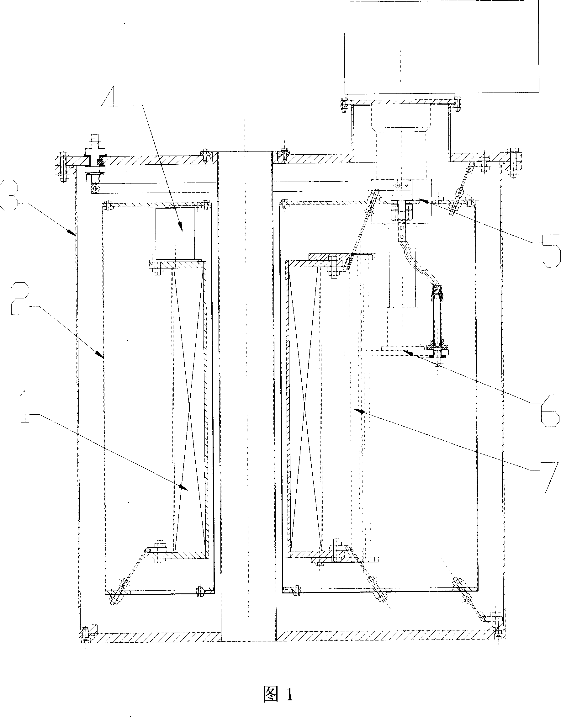
[0010] Figure 1 shows the structure of a conduction-cooled superconducting magnet. As shown in FIG. 1 , the primary cold head 5 of the refrigerator is connected to the cold shield 2 , and the thermal switch 4 of the present invention is installed between the cold shield 2 and the flange on the superconducting magnet 1 . The secondary cold head 6 of the refrigerator is connected with the magnet 1 through a cold conduction belt 7 . The magnet 1, the cold screen 2, the thermal switch 4, the primary cold head 5, the secondary cold head 6, and the cold conduction belt 7 are all placed in the cryogenic container 3.

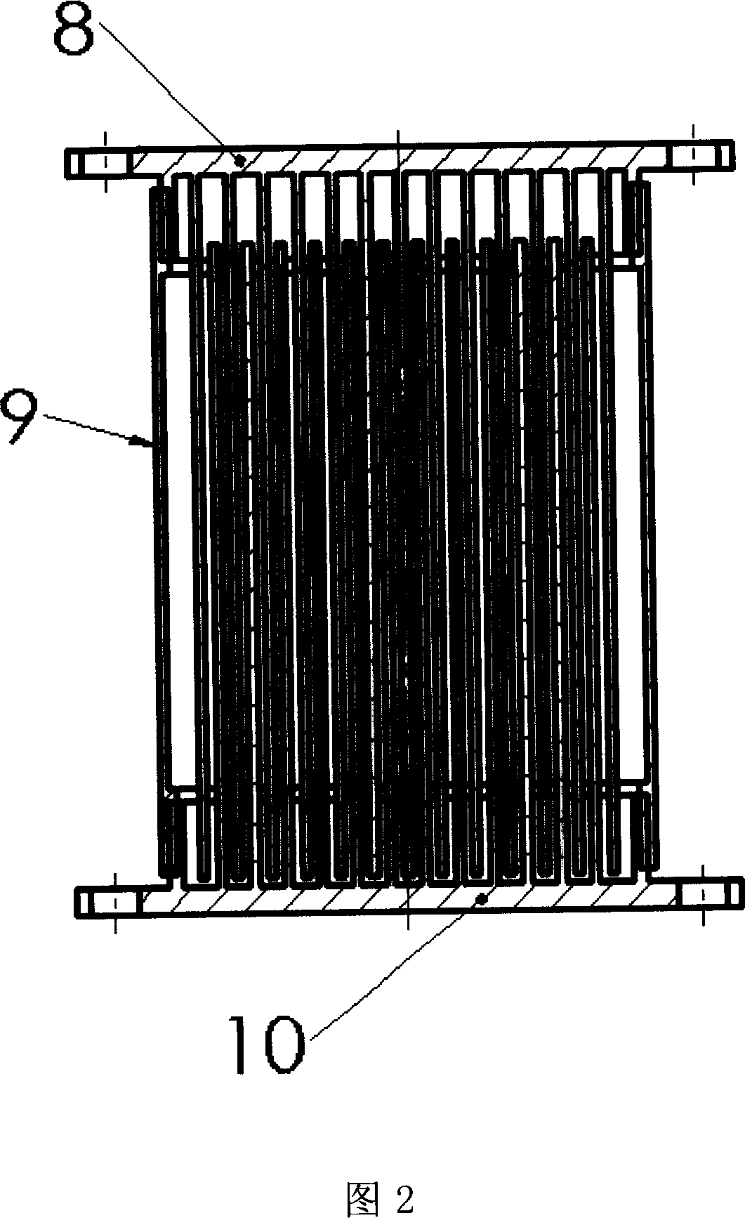
[0011] As shown in FIG. 2 , the thermal switch 4 of the present invention is a cylindrical pot-shaped airtight container, including an upper round end plate 8 , a lower round end plate 10 and a thin-walled cylinder 9 . Thin-walled cyli...


PUM


Abstract

The invention relates to a thermal switch for conduction-cooled superconducting magnet, characterized in that it is the cylinder closed accommodator, comprising upper round plate [8], low round plate [10] and cylinder with thin wall [9]; the cylinder with thin wall [9] is the wall surface of cylinder closed accommodator; parallel red copper fins arranged in certain distance are set on inner surfaces of upper round plate [8] and lower round plate [10], fins on upper and lower round plates insert in cross and there is gap between adjacent fins; upper round plate [8] and lower round plate [10] are made of high thermal conductivity material and the cylinder with thin wall [9] is made of low thermal conductivity material; upper round plate [8], lower round plate [10] and cylinder with thin wall [9] are connected by positive and negative screw thread and the length of thermal switch [4] on the axial direction is controlled by the rotating depth of cylinder with thin wall [9]. The invention is provided with no need to vacuum pumping, strong conduction ability, big on-off ratio and no need to be controlled by outside. It can shorten the cooling time of prior conducting cooled magnet system.

Description

technical field [0001] The invention relates to a thermal switch for low-temperature engineering, in particular to a thermal switch for conduction cooling superconducting magnets. Background technique [0002] Superconducting magnets must operate at low temperatures, and the conduction-cooled magnets are connected to the secondary cold head of the refrigerator. Because the efficiency of the secondary cold head of the refrigerator is very low, when the mass of the magnet is large, the cooling time of the magnet is very long. The efficiency of the primary cold head of the refrigerator is relatively high. In order to make full use of the cooling capacity of the first-stage cold head, a thermal switch can be used to connect the first-stage cold head to the magnet to shorten the cooling time of the magnet. The thermal switch as the thermal connection and thermal isolation between the primary cold head and the magnet should have high heat transfer efficiency and high reliability...

Claims


Application Information

Patent Timeline
IPC IPC(8): F28D15/02
Inventor 赵保志刁彦华王秋良戴银明雷源忠宋守森刘宏伟
Owner INST OF ELECTRICAL ENG CHINESE ACAD OF SCI
Why Eureka
Try Eureka