
Interferometer maintaining optical relationship between elements

A technology of interferometer and relationship, applied in the field of interferometer, can solve a lot of problems such as cost, user inconvenience, frustration, etc.

Active Publication Date: 2009-11-18
AGILENT TECH INC
View PDF2 Cites 15 Cited by
  • Summary
  • Abstract
  • Description
  • Claims
  • Application Information

AI Technical Summary

Problems solved by technology

Until now, however, such leaf springs / bearings have required periodic alignment when the interferometer's operating environment undergoes significant temperature changes
While the means for alignment are typically accomplished by an automatic alignment algorithm (actuated by a precision stepper motor), the need for alignment often arises at inopportune times, which results in significant user inconvenience and / or frustration
Additionally, achieving alignment will incur substantial costs (money and space)

Method used


Image

  • Interferometer maintaining optical relationship between elements
  • Interferometer maintaining optical relationship between elements
  • Interferometer maintaining optical relationship between elements

Examples


Embodiment Construction

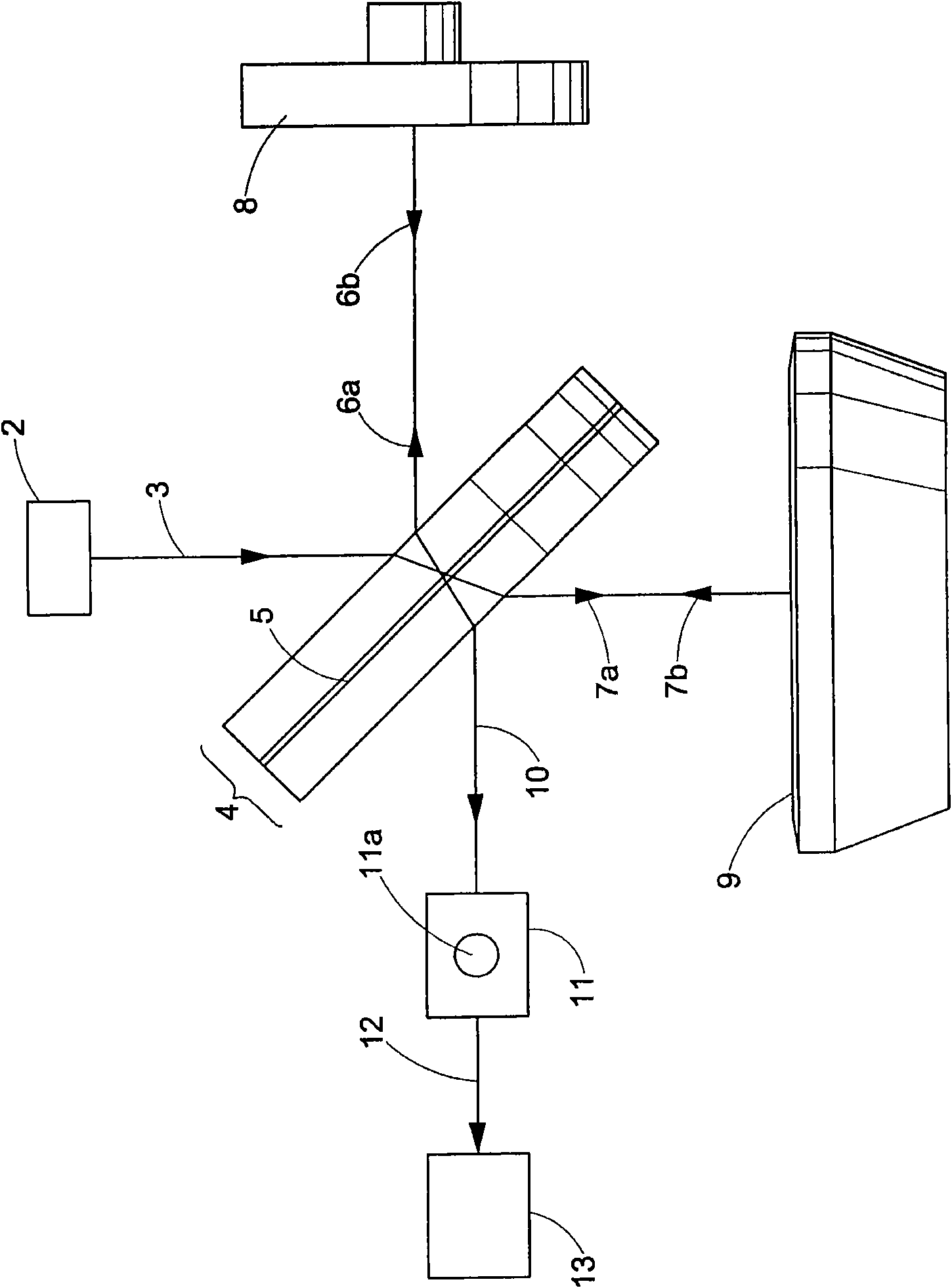
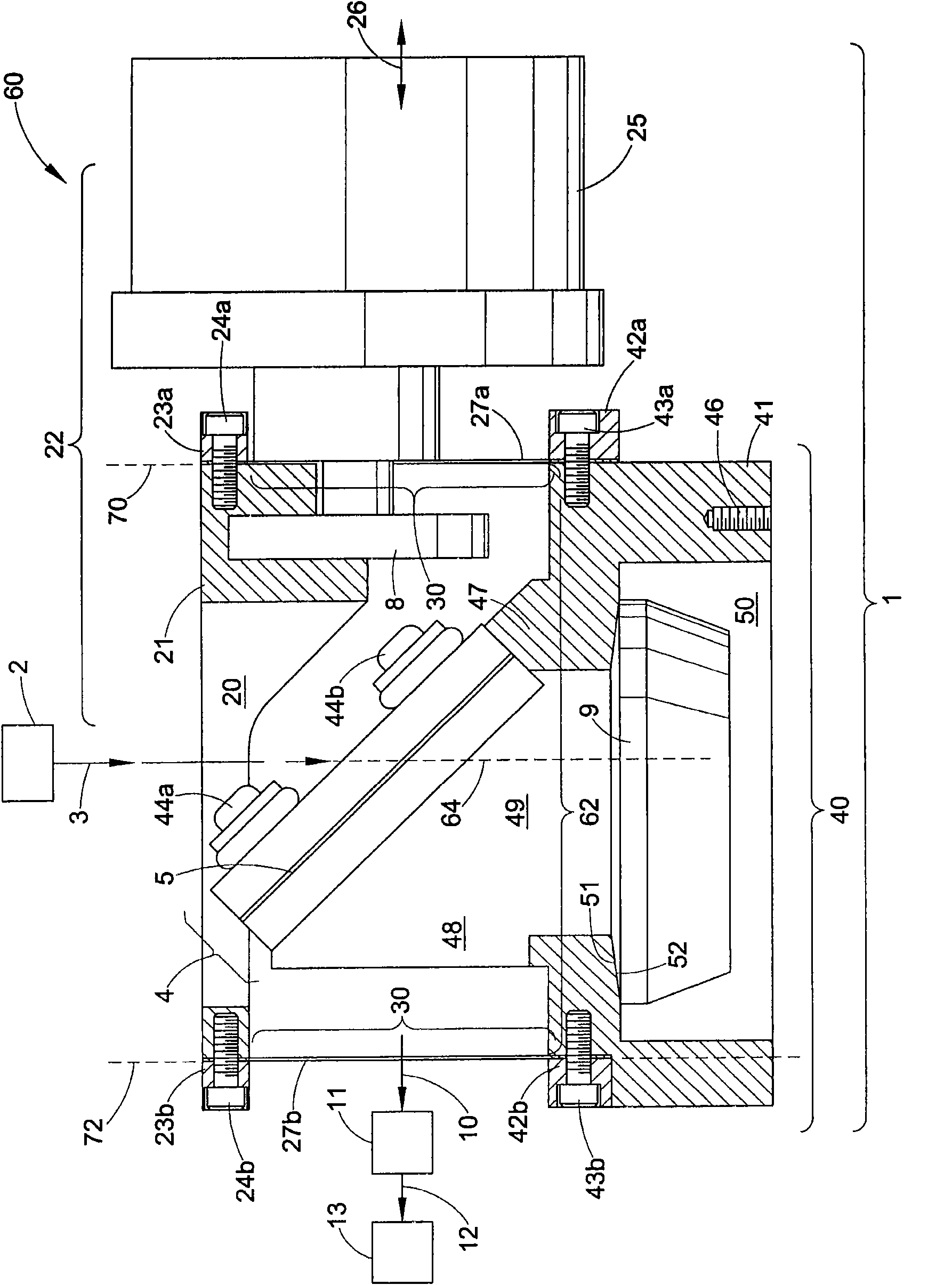
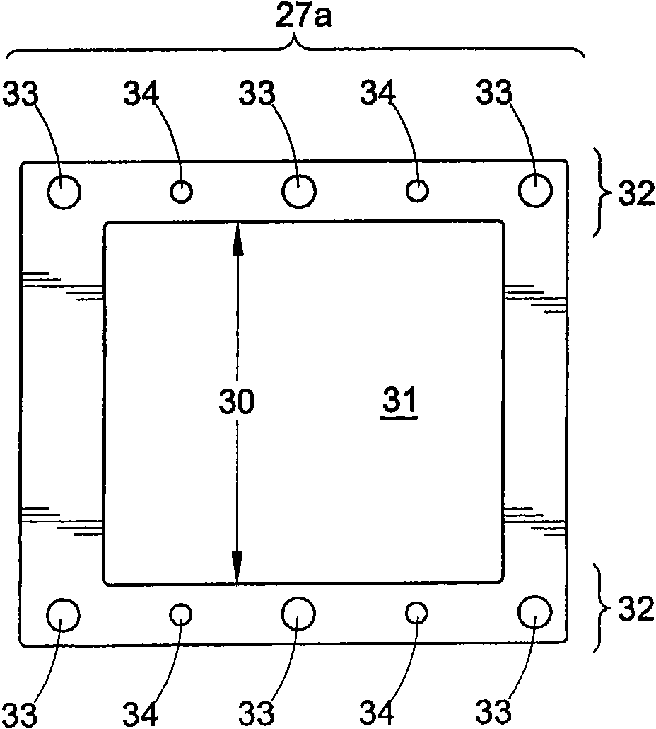
[0014] refer to figure 1 and 2 , the optical elements in the interferometer 1 shown according to the first embodiment of the present invention include a beam splitter 4 , a movable mirror 8 , and a fixed mirror 9 . Infrared rays 3 from an infrared light source 2 are guided to a beam splitter 4 comprising a beam splitting surface 5 . In one embodiment, the interferometer is used in a Fourier transform infrared (FTIR) spectrometer. The infrared rays 3 are divided by the beam splitting surface 5 into a reflection portion 6a and a transmission portion 7a. The reflected portion 6a goes on to the movable mirror 8 which reflects the reflected portion 6a back onto itself as reflected beam 6b back to the beam splitting surface 5 . In a similar fashion, the transmissive portion 7a goes on to the fixed mirror 9 which reflects the transmissive portion 7a back onto itself as reflected beam 7b back to the beam-splitting surface 5 . The reflected beams 6 b , 7 b coincide at the beam-spli...


PUM


Abstract

An interferometer for Fourier transform infrared spectroscopy includes a fixed assembly including a housing, a beam splitter, and a mirror fixedly positioned relative to each other. A movable assembly includes a housing, a mirror, and a motor coil, fixedly positioned relative to each other. A first flat spring has an opening for providing an unobstructed optical path of radiation therethrough. A first end of the first flat spring is secured to the fixed assembly and a second end of the first flat spring is secured to the movable assembly for providing movement of the movable assembly relative to the fixed assembly via the first flat spring. An optical relationship between the beam splitter, the mirror of the fixed assembly, and the mirror of the movable assembly is maintained independent of a distance between the movable assembly and the fixed assembly.

Description

technical field [0001] The present invention relates to interferometers. The invention has particular application in maintaining the alignment of an interferometer and will be described with specific reference thereto. It should be appreciated, however, that the invention may also be adapted for other applications. Background technique [0002] Known Michelson interferometers have many commercial applications. It is well known that slight misalignment of optical components can lead to modulation changes that can significantly affect interferometer performance. Numerous attempts have been made in the design of commercial interferometers, including Michelson interferometers, to ensure that misalignment is reduced, or that the effects of misalignment are reduced. Some such attempts have included passive means, such as the use of right-angle mirrors, retro-reflectors, and / or other means to compensate for undesired effects. Other such attempts include active devices, such as ...

Claims


Application Information

Patent Timeline
Patent Type & Authority Applications(China)
IPC IPC(8): G01J3/02G01J3/453G01B9/02
CPCG01J3/0202G01J3/4535G01J3/0286G01J3/02
Inventor G·雷斯勒D·W·施廷
Owner AGILENT TECH INC
Learn More