Vane type continuous rotating cylinder

A vane type and rotary cylinder technology, applied in the direction of rotary piston pumps, rotary piston machines, rotary piston engines, etc., can solve the problems of high processing difficulty, low energy conversion efficiency, non-continuous power output, etc. The effects of leakage loss, wide range of allowable working fluids, and wide torque output range

Inactive Publication Date: 2009-11-25
周华
View PDF0 Cites 18 Cited by
  • Summary
  • Abstract
  • Description
  • Claims
  • Application Information

AI Technical Summary

Problems solved by technology

[0003] Crankshaft-connecting-rod-piston mechanism, its structural feature is that the energy conversion is realized by the positive (reverse) conversion of linear reciprocating motion and rotary motion, the main disadvantages are non-uniform speed, non-equal torque, discontinuous power output, inertial impact, dead As a result, related machines need multi-level wrong-phase linkage, large vibration, high noise, low efficiency, low frequency of work, complex structure, and high processing difficulty
[0004] The turbine mechanism is characterized by the conversion process of fluid kinetic energy in the middle of the positive (reverse) conversion process of fl

Method used


Image

  • Vane type continuous rotating cylinder
  • Vane type continuous rotating cylinder
  • Vane type continuous rotating cylinder

Examples


no. 1 example

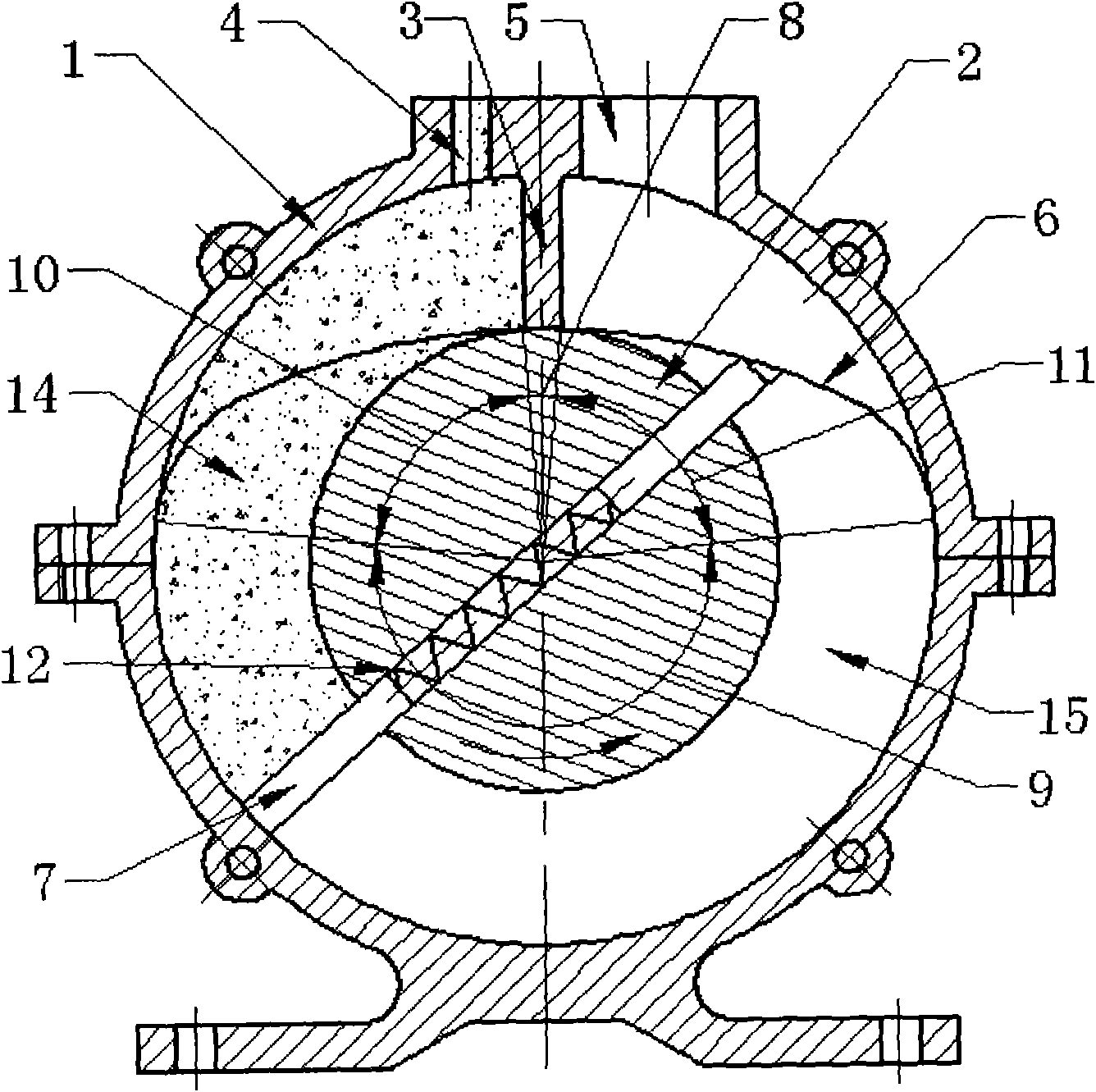
[0047] Such as figure 1 As shown, the vane-type continuous rotary cylinder of the present invention is similar in structure to the vane-type swing cylinder, including a cylinder body 1, a rotor 2, a partition 3, a working medium inlet 4, a working medium outlet 5, a cam 6, and a vane 7. Compared with the existing vane-type swing cylinder, there are more cams 6. The function of the cams 6 is to make the working vanes 7 displace in a plane parallel to or passing through the axis of the cylinder body, so that they can cross the partition plate 3 and perform work in a cycle, so as to realize single To the continuous circular motion mode. exist figure 1 The middle rotor 2, the cam 6 and the blades 7 form a concentric cam mechanism.

[0048] In the case of applying fluid pressure energy to mechanical energy, such as figure 1 As shown, an annular chamber is provided by the cylinder body 1 and the rotor 2, a partition 3 is arranged in the chamber, the working medium inlet 4 and ...

no. 2 example

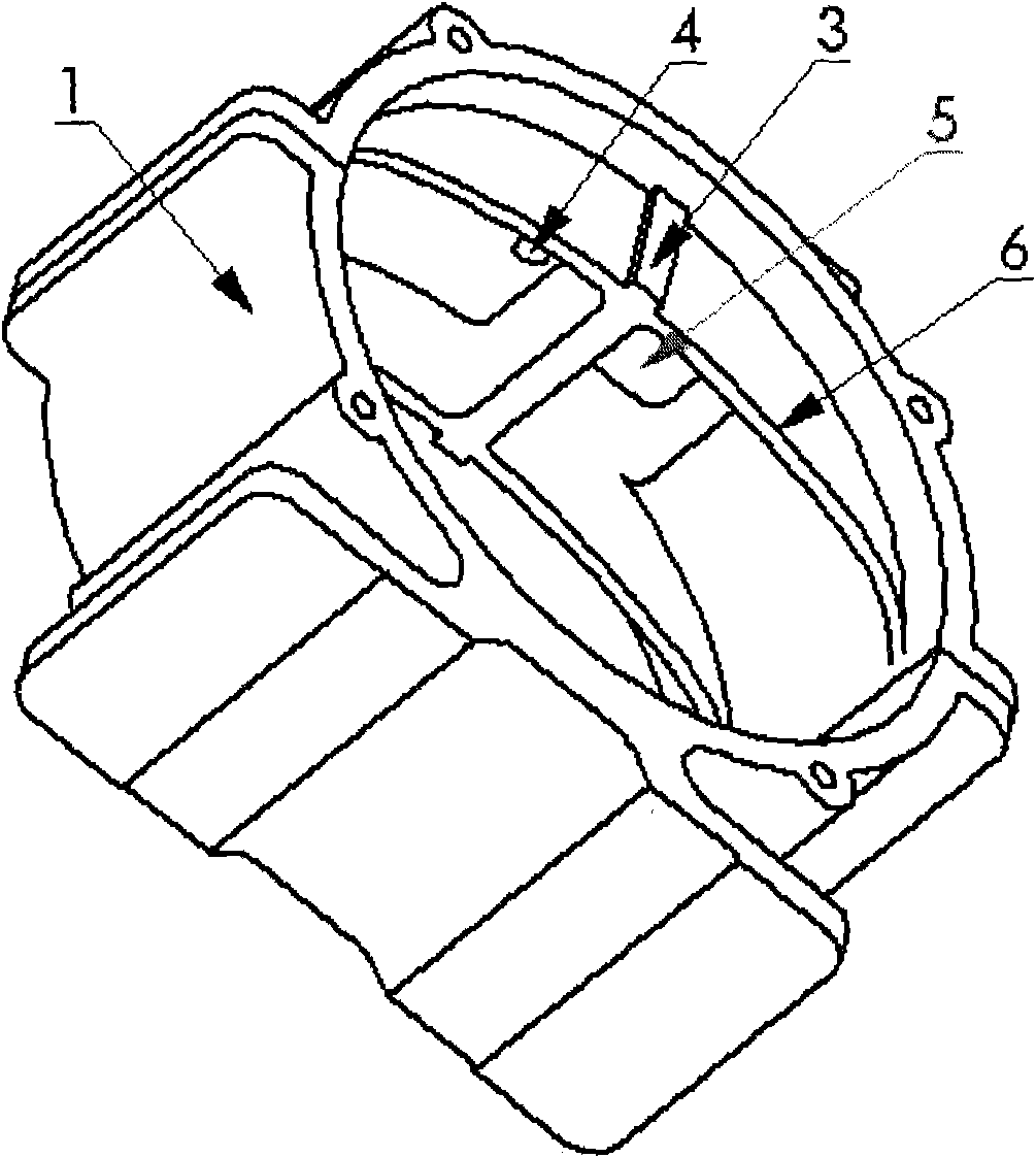
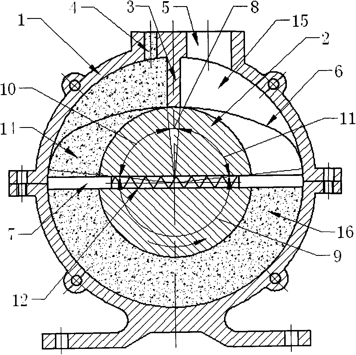
[0055] The difference from the first embodiment is that when the cam 6 is a disk-type male cam, the follower, that is, the blade 7, moves outside the cam and is located on the rotor 2 with the partition 3, as Figure 5 As shown, the vane 7 is arranged on the cylinder body 1. In the above-mentioned content, the near angle of repose 8 is interchanged with the far angle of repose 9, and the thrust motion angle 10 is interchanged with the return motion angle 11. In the annular chamber of the foregoing embodiment In this embodiment, the outer wall becomes the inner wall of the annular chamber, and other contents remain unchanged.

no. 3 example

[0057] Such as Figure 6 and Figure 7 As shown, the difference from the first embodiment is that the cam 6 is a cylindrical cam and is located in the cylinder body 1, and its working principle can be understood with reference to the description of the first embodiment. In addition, as shown in the second embodiment, a cylindrical cam can also be arranged on the rotor 2, and its working principle can be understood with reference to the description of the first embodiment and the second embodiment.

[0058] In addition, the cams in the foregoing embodiments can be appropriately deformed in combination with various technologies related to cam mechanisms in modern mechanical technology, typically including:

[0059] a. Design of the movement law of the follower

[0060] The blade 7 is used as a follower. When its mass is large, the momentum has a great influence on its motion, and the primary consideration is to reduce its maximum speed; when the requirement for its inertial fo...


PUM


Abstract

A vane type continuous rotating cylinder comprises a cylinder body (1), a rotor (2), a spacer (3), a working substance inlet (4), a working substance outlet (5) and a vane (7). The rotor is arranged in the cylinder body to form a ring chamber with the cylinder body. The spacer separates the continuous chamber of the ring chamber. The working substance inlet (4) and working substance outlet (5) are located respectively on both sides of the spacer. The vane type continuous rotating cylinder further comprises a cam (6) which guides the vane passing through the spacer.

Description

technical field [0001] The invention relates to a piston cylinder, in particular to a device similar to a vane type swing cylinder. Background technique [0002] At present, there are mainly crankshaft connecting rod piston mechanism, turbine mechanism and vane motor mechanism that are relatively mature in the forward (reverse) conversion of fluid pressure energy and mechanical energy in the form of continuous circular rotation. [0003] Crankshaft-connecting-rod-piston mechanism, its structural feature is that the energy conversion is realized by the positive (reverse) conversion of linear reciprocating motion and rotary motion, the main disadvantages are non-uniform speed, non-equal torque, discontinuous power output, inertial impact, dead As a result, the relevant machines need multi-stage wrong-phase linkage, large vibration, high noise, low efficiency, low frequency of work, complex structure, and high processing difficulty. [0004] The turbine mechanism is characteri...

Claims


Application Information

Patent Timeline
IPC IPC(8): F01C1/344F04C2/344
CPCF04C2/344F04C2/44F01C21/106F04C2240/30F04C9/002F01C21/10F04C15/06
Inventor 周华
Owner 周华
Why Eureka
Try Eureka