Rolling bearing root part for support hanger

A technology of rolling bearings and hangers, which is applied in the direction of pipeline supports, pipes/pipe joints/fittings, mechanical equipment, etc., can solve the problem of not meeting the monitoring requirements of support and hanger systems, affecting the normal operation of piping systems and equipment, and failing to fully reflect Thermal expansion and other issues, to achieve the effect of convenient design and installation, reduced civil structure, and simplified design

Inactive Publication Date: 2010-12-29
申松林
View PDF6 Cites 0 Cited by
  • Summary
  • Abstract
  • Description
  • Claims
  • Application Information

AI Technical Summary

Problems solved by technology

[0003] However, when the hanger is used for partial installation, the inclined hanger will generate horizontal additional force on the piping system
In the design specification, the maximum allowable deflection angle is 4°, and the corresponding horizontal additional force is 7% of the load of the support and hanger; if the bracket sliding plate or the hanger roller part is used, due to the The friction coefficient is relatively large, the friction coefficient of the polytetrafluoroethylene sliding plate (and steel plate) is ~0.1, the friction coefficient of the sliding shaft working surface (steel and steel) of the roller part is ~0.15, and the corresponding horizontal additional force is the load of the support and hanger 10-15% of that; these additional forces are transferred to the equipment interface and civil structure through the piping system, which will affect the normal operation of the piping system and equipment and reduce the safety of the project
[0004] The special displacement indicator can only mark the local thermal displacement of the piping system, and cannot fully reflect the thermal expansion of the entire piping system, so it cannot meet the requirements for monitoring the operation of the support and hanger system

Method used


Image

  • Rolling bearing root part for support hanger
  • Rolling bearing root part for support hanger
  • Rolling bearing root part for support hanger

Examples


Embodiment 1

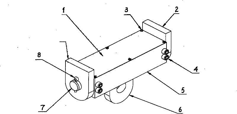
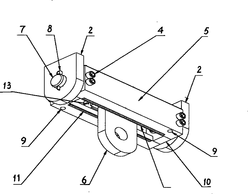
[0044] See attached figure 1 , 2 . This embodiment is a root part of a one-way hanger rolling bearing, which consists of a trolley guard plate 1, a welding side piece 2, a trolley fastening screw 3, a trolley fastening bolt 4, a trolley guide rail 5, a pin shaft 7, a pin 8, and a level bubble 9. The trolley guide rail end block 10, the trolley scale 11, the guide rail ball flat groove 12, and the first inner assembly 13 are jointly composed.

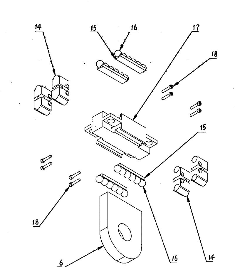
[0045] See attached image 3 . The first inner assembly 13 is composed of the eyelet welding piece 6, the trolley ball guide ring 14, the ball groove 15, the trolley ball 16, the trolley flat shaft 17, and the trolley second bolt 18. One end of the eyelet welding piece 6 is arc-shaped, and the other end is a plane end, and a round hole is opened in the arc-shaped end; the plane end of the eyelet welding piece 6 is welded on the bottom plate of the flat shaft 17 of the trolley, and the flat shaft 17 of the trolley is cross-shaped The...

Embodiment 2

[0052] See attached Figure 5 . This embodiment is a root component of a one-way bracket rolling bearing. In this embodiment, the basic structure of the root part of the rolling bearing of the support and hanger is the same as that of Embodiment 1, the difference lies in the welding sheet 6 with eyes and the guard plate 1 without trolley; in Embodiment 2, the root part of the rolling bearing of the support and hanger is turned up and down 180 degrees, Turn the side with the level bubble 9 and the trolley scale 11 upwards, no longer use the trolley guard plate 1, and weld the plane end of the welding side piece 2 to the lower civil structure; Its inner end is welded on the base plate of dolly flat shaft 17, and the outer end is provided with the band plate welded piece 19 of plate structure, and the face of band plate welded piece 19 is upwards, and plate structure can allow support tube support. The effect of this structural modification is to make the root part of the hange...

Embodiment 3

[0054] See attached Image 6 , 7 . This embodiment is a two-way hanger rolling bearing root part, which consists of a second inner assembly 33, a cart upper guard plate 20, a cart fastening screw 21, a cart guide rail 22, a ball guide groove 23, and a cart guide rail end plate 24, cart fastening bolt 25, cart scale 26 form jointly. Wherein the second inner assembly 33 is composed of the first inner assembly 13, trolley guide rail 5, guide rail ball flat groove 12, trolley guide rail end block 10, level bubble 9, trolley scale 11, cart second bolt 27, cart ball guide Ring 28, cart ball groove 29, cart ball 30, cart third bolt 31, cart ball guide ring fixed plate 32 form together;

[0055] See attached Figure 9 , is part of the structure of the second inner assembly 33, wherein the structure of the first inner assembly 13 is the same as that of embodiment 1;

[0056] The trolley guide rail 5 has two left and right sides, and grooves are formed on the inner side thereof, an...


PUM


Abstract

The invention discloses a rolling bearing root part for a support hanger, comprising a foraminate welding slice, a trolley upper protective plate, a welding side slice, trolley guide rails, a pin shaft, a level bubble, a trolley guide rail end block, a trolley scale, a first inside assembly, a second inside assembly, a cart upper protective plate, a cart fastening screw, cart rails, a rolling ballguide groove, a cart guide rail end block and a cart scale, wherein the first inside assembly is inlaid in the trolley guide rails through a rolling ball interface thereof, the second inside assemblyis inlaid in the cart rails through a rolling ball interface thereof, the level bubble and the scale are arranged at the lower end of each trolley guide rail, and the scale is arranged at the lower end of each cart rail. The invention has the advantages that the rolling bearing root part for the support hanger has little frictional resistance coefficient to greatly reduce additional force of thesupport hanger to piping thermal expansion, can mark two dimensional displacement, can enhance the safety of running of piping equipment, enable the equipment running to be more stable, reduces the maintenance time, prolongs the service life, enhances the comprehensive benefit of construction, and can be widely applied to industries such as the power industry, the petrochemical industry, the metallurgical industry and the like.

Description

【Technical field】 [0001] The invention relates to the technical fields of industrial engineering, pipeline laying, mechanical installation and maintenance, in particular to an accessory of a high-temperature pipeline support and hanger. 【Background technique】 [0002] At present, in the construction of industrial enterprises, especially when it involves the construction of high-temperature pipelines, for high-temperature pipelines in the vertical plane direction of the support and hanger due to large thermal displacement due to high temperature, the root of the support and hanger or the pipe part are often installed sideways. , and limit the partial installation angle of the tie rod, or use the technology of sliding plate and roller parts for installation. In addition, for the indication of the large thermal displacement of the piping system in the vertical plane direction of the support and hanger due to high temperature, the prior art solves it by setting special displacem...

Claims


Application Information

Patent Timeline
Patent Type & Authority Patents(China)
IPC IPC(8): F16L3/16
Inventor 申松林
Owner 申松林
Why Eureka
Try Eureka