
Method for calibrating structure light vision transducer based on one-dimensional target drone

A technology of visual sensor and calibration method, which is applied in the direction of instruments, optical devices, measuring devices, etc., and can solve the problem of not being able to calibrate a single camera

Inactive Publication Date: 2009-11-25
BEIHANG UNIV
View PDF1 Cites 19 Cited by
  • Summary
  • Abstract
  • Description
  • Claims
  • Application Information

AI Technical Summary

Problems solved by technology

In "Multi-camera calibration based on one-dimensional calibration object, Acta Automatica Sinica, Vol. 33, No. 3, 2007, 225-231", proposed a camera calibration method using a one-dimensional target that performs arbitrary rigid body motion. Calibration method, but this calibration method is only suitable for calibrating multiple cameras, not single camera

Method used


Image

  • Method for calibrating structure light vision transducer based on one-dimensional target drone
  • Method for calibrating structure light vision transducer based on one-dimensional target drone
  • Method for calibrating structure light vision transducer based on one-dimensional target drone

Examples


Embodiment Construction

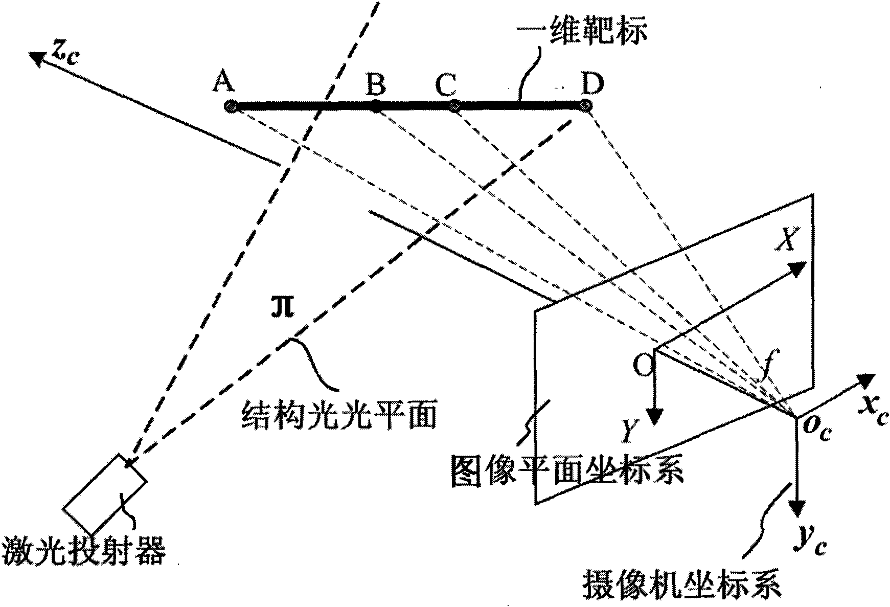
[0040] Before introducing the present invention, at first, see figure 1 The schematic diagram of the structured light vision sensor model is shown to illustrate the mathematical model of the structured light vision sensor. figure 1 shows the geometric structure relationship of the structured light three-dimensional visual perspective projection model, where O c -x c the y c z c (for the right-hand system) is the camera coordinate system, o i -XY is the image plane coordinate system, π is the structured light plane. A point in the camera coordinate system (x c ,y c ,z c ) and the point (X, Y) of the image plane coordinate system can be expressed by the following formula:

[0041] ρ · X Y 1 = F · x ...


PUM


Abstract

The invention provides a method for calibrating structure light vision transducer based on one-dimensional target drone, the method comprises: calibrating video camera interior parameters; arranging the one-dimensional target drone on different positions to calculate space coordinates of different crosses of one-dimensional target drones on different positions and the light plane as space coordinates of light plane different characteristic points; fitting the light plane equations by the obtained space coordinates of light plane different characteristic points. According to the invention, the structure light vision transducer can be calibrated by arranging the one-dimensional target drone arbitrarily on the position intersected with the light plane, the calibration is flexible, without auxiliary apparatuses.

Description

technical field [0001] The invention relates to a structured light vision measurement technology, in particular to a calibration method for a structured light vision sensor based on a one-dimensional target. Background technique [0002] Structured light vision measurement is based on the optical triangulation measurement principle. A certain pattern of structured light is projected on the surface of the object through an optical projector (it can be a laser projector or a projector), and a three-dimensional image of light strips modulated by the surface shape of the measured object is formed on the surface. The three-dimensional image is captured by a camera at another position, so as to obtain a two-dimensional distorted image of the light strip. The degree of distortion of the light bar depends on the relative position between the optical projector and the camera and the height of the surface profile of the object. Intuitively, displacements (or offsets) along a light s...

Claims


Application Information

Patent Timeline
Patent Type & Authority Applications(China)
IPC IPC(8): G01B11/00G01B11/25
Inventor 张广军曹黎俊魏振忠孙军华
Owner BEIHANG UNIV
Learn More