Full optical fibre quarter-wave plate and preparation method thereof

An all-fiber, wave plate technology, applied in the direction of cladding fiber, optical waveguide light guide, optical waveguide coupling, etc., can solve the problems of difficulty, increase system cost, and large optical loss.

Inactive Publication Date: 2009-11-25
COMCORE OPTICAL TECH
View PDF0 Cites 11 Cited by
  • Summary
  • Abstract
  • Description
  • Claims
  • Application Information

AI Technical Summary

Problems solved by technology

If the optical path goes back and forth once, that is, through four splicing points, the optical loss caused by the splicing points is relatively large
In addition, due to the ordinary linear birefringent fiber, whether it is stress birefringence (such as panda fiber) or geometric birefringence fiber (elliptical core fiber), the beat length is generally relatively short, about 2mm to 6mm, so it is necessary to make use of them directly. The length of the quarter-wave plate is only 0.5mm to 1.5mm, so it is really not easy to precisely control the length of the birefringent fiber to make the quarter-wave plate, unless a special long-wavelength fiber is used. Take a long elliptical core fiber, which will increase the cost of the system
However, it still cannot solve the problem of fusion splice loss between elliptical core fiber and circular core fiber

Method used


Image

  • Full optical fibre quarter-wave plate and preparation method thereof
  • Full optical fibre quarter-wave plate and preparation method thereof
  • Full optical fibre quarter-wave plate and preparation method thereof

Examples


Embodiment Construction

[0026] In general, the preparation steps are as follows:

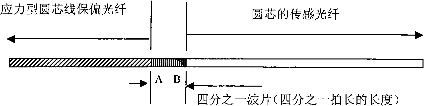
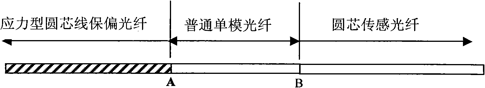
[0027] Step 1: Splice the stress-type round-core polarization-maintaining fiber with a small section of ordinary single-mode fiber, the fusion point is A, and then connect one end of a sensing fiber to the other end of this small section of ordinary single-mode fiber One end is welded together, and its welding point is B (see figure 2 ), the length of the single-mode optical fiber used may be 1.0 cm to 8.0 cm. The working parameters of the single-mode fiber spliced ​​here are basically the same as those of the line polarization-maintaining fiber. The purpose is to obtain a relatively low splice loss, which can generally be guaranteed to be less than 0.1dB;

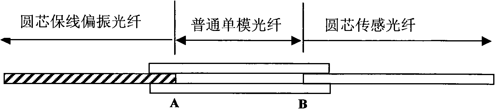
[0028] The second step is to take two optical fibers (which can be at least one of single-mode optical fiber, multi-mode optical fiber and coreless fiber) whose diameter is the same as or close to the above-mentioned section of ordinary optical fiber, and place t...


PUM


Abstract

The invention discloses a preparation method of a full optical fibre quarter-wave plate, which comprises the following steps: step1, splicing one end of a circular core wire polarization-preserving optical fibre used for transmission and one end of a section of single mode optical fibre in a fusion mode, and splicing one end of a circular core sensing optical fibre with the other end of the single mode optical fibre in a fusion mode; step 2, taking at least a section of the optical fibre as an auxiliary optical fibre, placing the auxiliary optical fibre to be parallel and abutting against one side or both sides of the single mode optical fibre of the spliced fibre structure in the step 1, and making a main shaft of the circular core wire polarization-preserving optical fibre form an angle of 45 DEG with a placed plane; and step 3, heating and melting concatenated single mode optical fibre areas with high temperature, making the single mode optical fibre of the heating area and the auxiliary fibre achieve a melting state and be melted together, continuously heating and making the single mode optical fibre of a circular core gradually be elliptical, and controlling the heating and welding time to prepare and form the quarter-wave plate. The preparation method utilizes common single mode optical fibres to prepare the quarter-wave plate with tiny loss, and also can be used for preparing other set wave plates.

Description

technical field [0001] The invention relates to a quarter-wave plate in an all-fiber current sensor, and also relates to a preparation method thereof. Background technique [0002] At present, fiber-optic quarter-wave plates are widely used, especially in fiber-optic current sensors. Through it, the linearly polarized positive light from the linear birefringent fiber can be transformed into circularly polarized light, and then enter the sensing fiber after output. Typically in fiber-optic current sensors, a quarter-wave plate is placed between the linear birefringent polarization-maintaining fiber and the sensing fiber. The all-fiber quarter-wave plate is actually a section of birefringent fiber with a length of one-fourth beat length, which is usually the same as the linear polarization-maintaining fiber, except that it has a certain distance from the main axis of the transmission fiber (line polarization-maintaining fiber) during fusion splicing. 45 degree included angle...

Claims


Application Information

Patent Timeline
Patent Type & Authority Applications(China)
IPC IPC(8): G02B5/30G02B6/255G02B6/02G01R15/24
Inventor 黄勇
Owner COMCORE OPTICAL TECH
Why Eureka
Try Eureka