Electronic endoscope apparatus
An electronic endoscope and electronic component technology, which is applied in the field of electronic endoscope devices, can solve the problems of difficulty in holding, poor operability, and hindering the reduction of the diameter of the insertion portion, and achieves the effect of preventing the diameter from becoming larger and preventing the increase in size.
- Summary
- Abstract
- Description
- Claims
- Application Information
AI Technical Summary
Problems solved by technology
Method used
Image

Examples
no. 1 approach
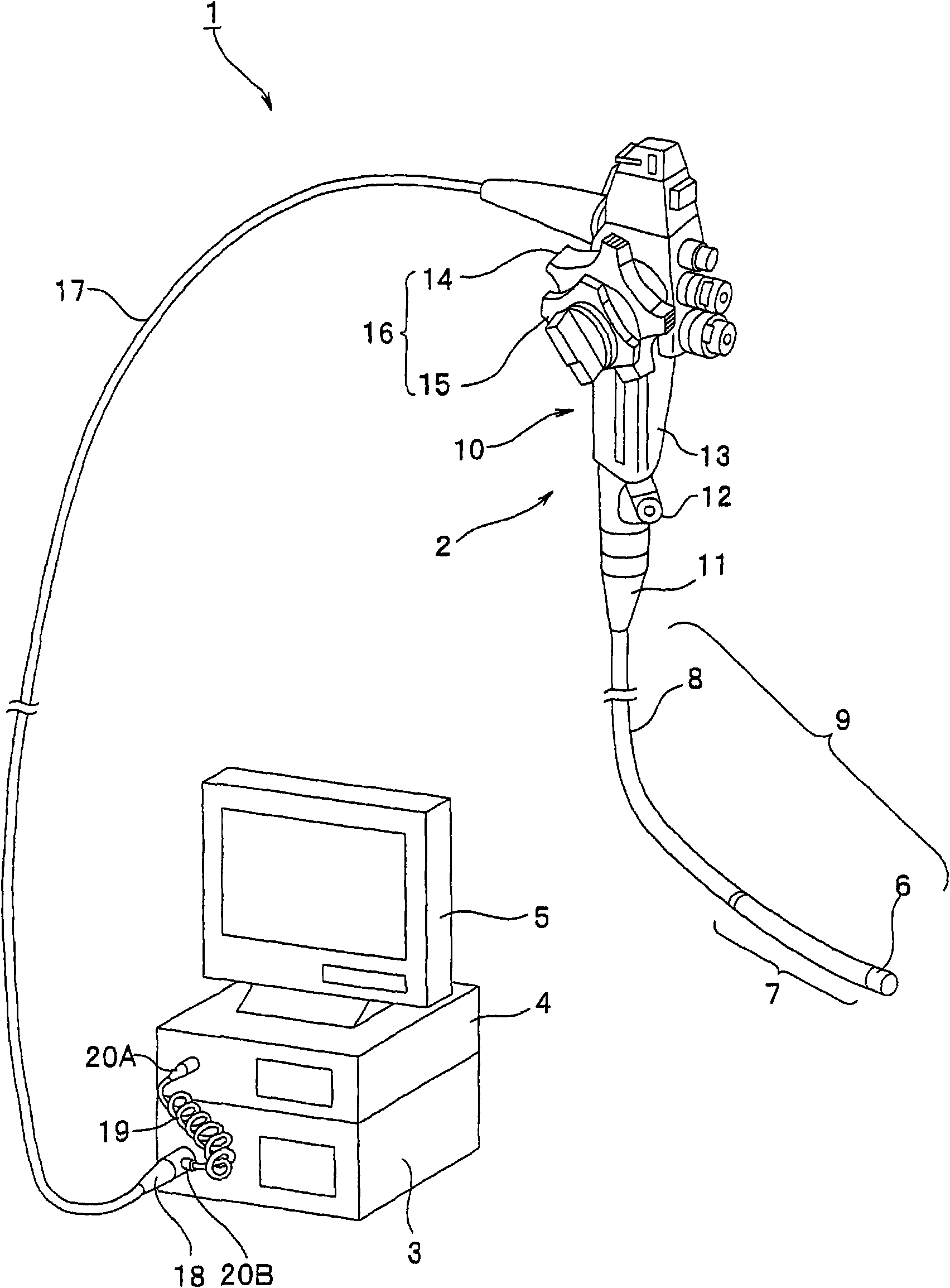
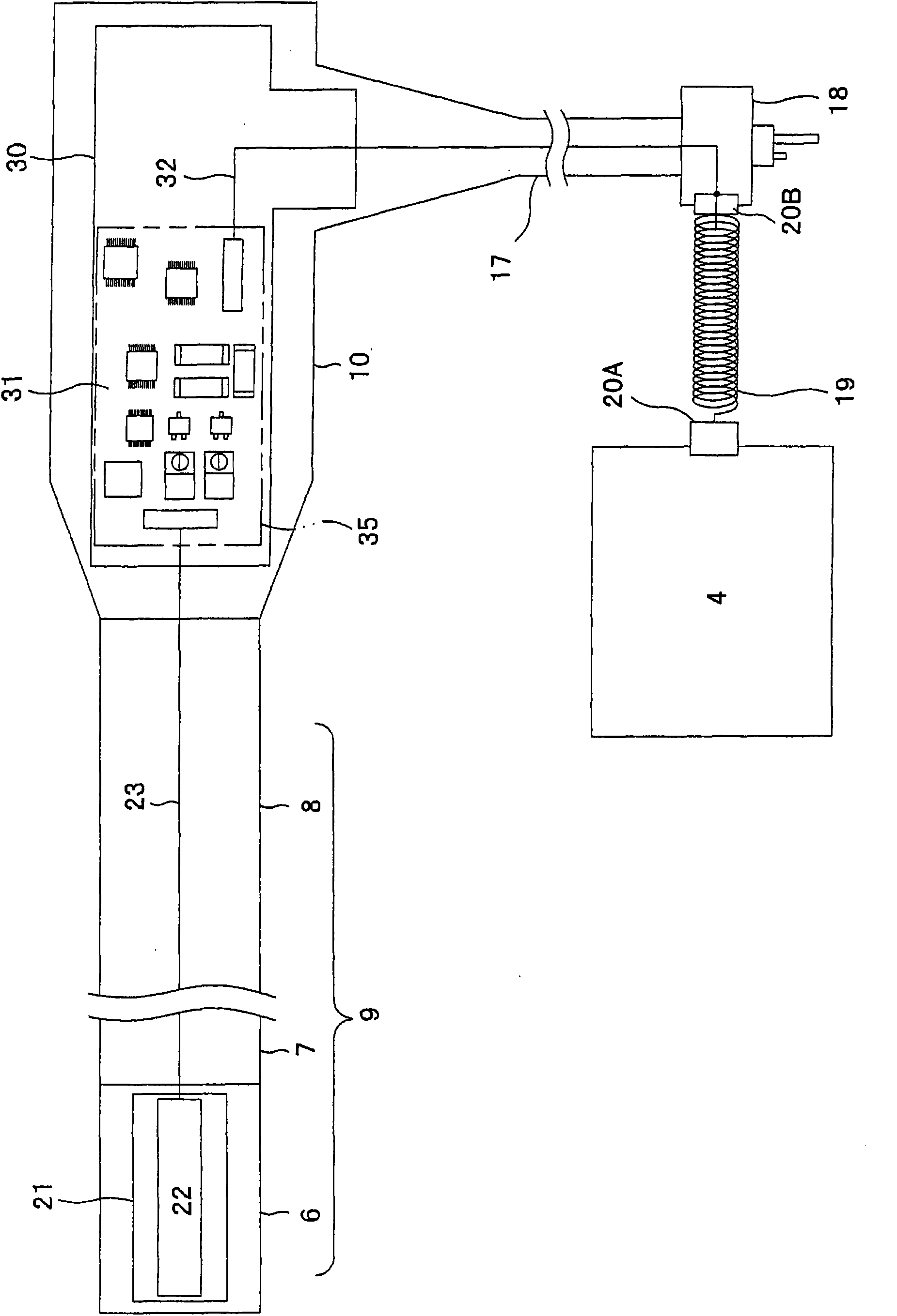
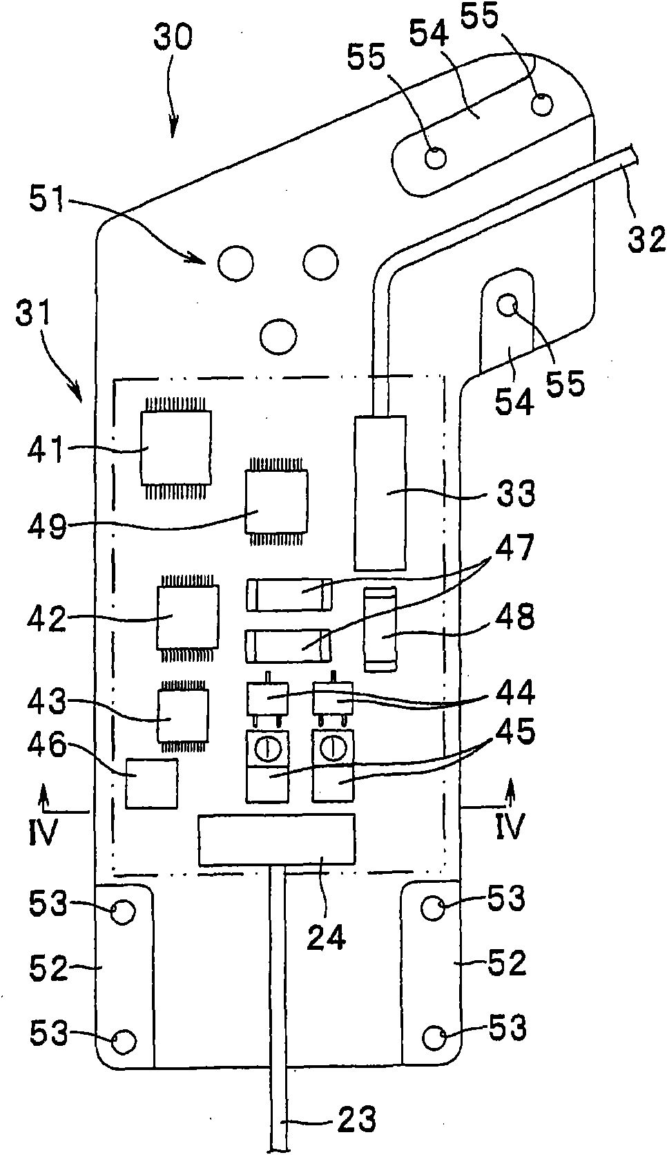
[0032] First, use Figure 1 to Figure 5 The first embodiment of the present invention will be described. In addition, Figure 1 to Figure 5 Relates to the first embodiment of the present invention, figure 1 Is a diagram showing the structure of an electronic endoscope system, figure 2 Is a block diagram showing the electrical connection structure of the electronic endoscope system, image 3 Is a diagram showing the structure of an electronic circuit board, Figure 4 Is along image 3 A cross-sectional view of the electronic circuit board of the IV-IV line, Figure 5 It is a diagram showing the electrical connection between the plug-in part and the integrated shielding part of the universal cable and the electronic circuit board, Figure 6 It is a perspective view for explaining the internal structure of the insertion part and the universal cable, Figure 7 Is a perspective view showing the insertion part and one end of the universal cable, Figure 8 Is a plan view showing the st...
no. 2 approach
[0065] Next, the following usesPicture 10 with Picture 11 The second embodiment of the present invention will be described.
[0066] In addition, Picture 10 with Picture 11 Related to the second embodiment of the present invention, Picture 10 It is a diagram mainly used to explain the positional relationship between the electronic circuit board in the operation unit and the insertion channel of the treatment instrument. Picture 11 Is along Picture 10 The figure viewed by the arrow VII is a figure mainly used to explain the positional relationship between the electronic circuit board in the operation unit and the insertion channel of the treatment instrument. In addition, in the following description, the same reference numerals are used for the same components as those of the above-mentioned first embodiment, and detailed descriptions and effects of these structures are omitted.
[0067] For the electronic endoscope device 2 of this embodiment, such as Picture 10 with Pict...
no. 3 approach
[0079] Next, the following uses Figure 12 to Figure 15 The third embodiment of the present invention will be described.
[0080] In addition, Figure 12 to Figure 15 Related to the third embodiment of the present invention, Picture 12 It is a diagram showing a circuit board portion formed by a flexible printed circuit board on which various electronic components are mounted in an unfolded state on a frame member, Figure 13 Is shown Picture 12 A diagram of the circuit board portion in which the flexible printed circuit board arranged on the frame member is deformed so as to surround various electronic components mounted on it, Figure 14 Yes Figure 13 A cross-sectional view of the circuit board portion arranged on the frame member in a state of Figure 15 It is a cross-sectional view showing the structure of a flexible printed circuit board. In addition, in the following description, the same reference numerals are used for the same components as those of the above-mentioned f...
PUM
| Property | Measurement | Unit |
|---|---|---|
| Length | aaaaa | aaaaa |
Abstract
Description
Claims
Application Information
 - R&D
- Intellectual Property
- Life Sciences
- Materials
- Tech Scout
- Unparalleled Data Quality
- Higher Quality Content
- 60% Fewer Hallucinations
Browse by: Latest US Patents, China's latest patents, Technical Efficacy Thesaurus, Application Domain, Technology Topic, Popular Technical Reports.
© 2025 PatSnap. All rights reserved.Legal|Privacy policy|Modern Slavery Act Transparency Statement|Sitemap|About US| Contact US: help@patsnap.com