
Digital locking indictor, phase lock loop frequency synthesizer and wireless transceiver

A frequency synthesizer and digital locking technology, which is applied in the field of communication, can solve problems such as limited leakage current, failure to work normally, and inability to realize digitization, and achieve the effects of overcoming leakage current, adjustable precision, and eliminating false locking indications

Inactive Publication Date: 2009-11-25
INST OF MICROELECTRONICS CHINESE ACAD OF SCI
View PDF0 Cites 15 Cited by
  • Summary
  • Abstract
  • Description
  • Claims
  • Application Information

AI Technical Summary

Problems solved by technology

The analog lock indicator is not sensitive to leakage current and is suitable for applications where the reference frequency is relatively high, but it requires an external filter, the filter design is cumbersome, the response of the lock and unlock indication is slow, and it is not suitable for integration with the baseband
The digital lock indicator has the characteristics of quick response and simple design. It is easy to apply to the occasion of integration with the baseband. It is the future development trend. However, the accuracy of the digital lock indicator depends on the reference frequency and is limited by the leakage current. When the phenomenon occurs, it cannot work normally, and the delay circuit is generated by passive components, so it cannot be fully digitalized

Method used

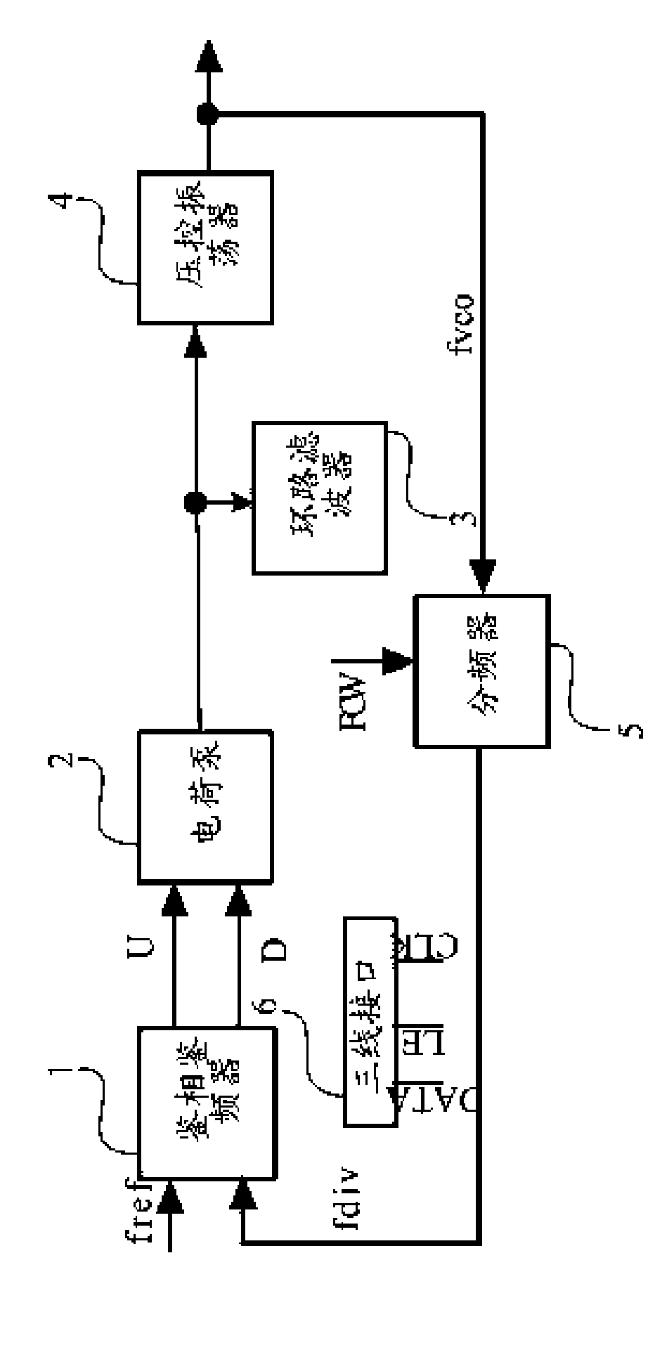
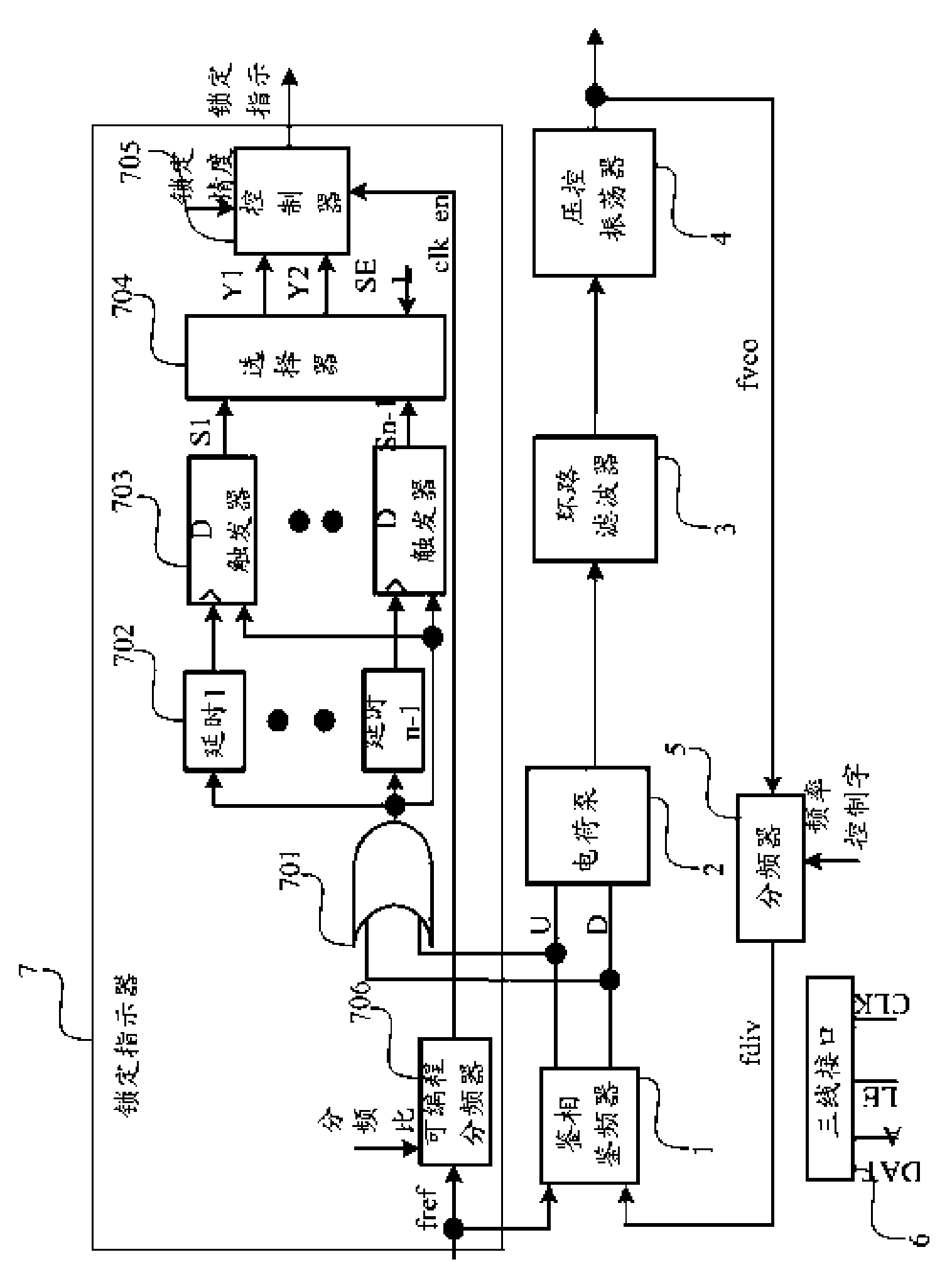

Image

  • Digital locking indictor, phase lock loop frequency synthesizer and wireless transceiver
  • Digital locking indictor, phase lock loop frequency synthesizer and wireless transceiver
  • Digital locking indictor, phase lock loop frequency synthesizer and wireless transceiver

Examples


Embodiment Construction

[0029] In order to make the object, technical solution and advantages of the present invention clearer, the implementation manner of the present invention will be further described in detail below in conjunction with the accompanying drawings.

[0030] Such as figure 2 As shown, the phase-locked loop frequency synthesizer provided by the embodiment of the present invention includes: a phase-detection-frequency detector 1, a charge pump 2, a loop filter 3, a voltage-controlled oscillator 4 and a phase-detection-frequency detector connected in sequence A frequency divider 5 between the input terminal of the voltage control oscillator and the output terminal of the voltage-controlled oscillator 4, a three-phase interface 6 and a digital lock indicator 7; wherein the digital lock indicator 7 includes: an OR gate 701, a plurality of sets of delay circuits 702, Multiple sets of D flip-flops 703 , a selector 704 , a controller 705 and a programmable frequency divider 706 . Each com...


PUM


Abstract

This invention discloses a digital locking indictor, comprising a joint gate, a delay circuit, a trigger set, a selector and a controller, which are sequentially connected. This invention further discloses a phase lock loop frequency synthesizer, comprising a phase detection discriminator, a charge pump, a loop filer, a voltage-controlled oscillator, a frequency divider and a digital locking indictor, which are sequentially connected. The digital locking indictor comprises a joint gate, a delay circuit, a trigger set, a selector and a controller, which are sequentially connected. This invention further discloses a wireless transceiver, comprising a phase lock loop frequency synthesizer. The phase lock loop frequency synthesizer comprises a digital locking indicator. The digital locking indicator comprises a joint gate, a delay circuit, a trigger set, a selector and a controller, which are sequentially connected. The precision of the locking indicator can be adjusted by using this invention; the influence due to the current leaked by the charge pump can be effectively conquered because the locking indicator is insensitive to the reference frequency. And the phenomenon of wrong locking indication caused by cycle slip can be eliminated.

Description

technical field [0001] The invention relates to the communication field, in particular to a digital lock indicator, a phase-locked loop frequency synthesizer and a wireless transceiver. Background technique [0002] The phase-locked loop frequency synthesizer is a key module in the design of the wireless transceiver. It outputs a series of high-precision frequency signals to provide local oscillator signals for the frequency conversion of the transceiver. The commonly used phase-locked loop frequency synthesizer structure is as follows figure 1 As shown, the phase and frequency detector 1, the charge pump 2, the loop filter 3, the voltage-controlled oscillator 4 connected in sequence and between the input of the phase-frequency detector 1 and the output of the voltage-controlled oscillator 4 The frequency divider 5 constitutes. The phase and frequency discriminator 1 compares the phase difference and frequency difference between the output of the frequency divider 5 and th...

Claims


Application Information

Patent Timeline
Patent Type & Authority Applications(China)
IPC IPC(8): H03L7/08
Inventor 黄水龙王小松张海英
Owner INST OF MICROELECTRONICS CHINESE ACAD OF SCI
Learn More