Image display device, display method thereof, program, integrated circuit, glasses type head mounted display, automobile, binoculars, and desktop type display

An image display device and image technology, applied in image communication, television, instruments, etc., can solve the problems of changing frame rate or resolution, difficulty in improving image resolution, viewing angle, frame rate, etc.

Inactive Publication Date: 2009-11-25
PANASONIC CORP
View PDF2 Cites 35 Cited by
  • Summary
  • Abstract
  • Description
  • Claims
  • Application Information

AI Technical Summary

Problems solved by technology

[0007] However, there is a problem in the display device of the laser scanning method that it is difficult to improve the image quality such as resolution, viewing angle, and frame rate of the displayed image.
However, with this method, the size of the displayed image is determined according to t...

Method used


Image

  • Image display device, display method thereof, program, integrated circuit, glasses type head mounted display, automobile, binoculars, and desktop type display
  • Image display device, display method thereof, program, integrated circuit, glasses type head mounted display, automobile, binoculars, and desktop type display
  • Image display device, display method thereof, program, integrated circuit, glasses type head mounted display, automobile, binoculars, and desktop type display

Examples


no. 1 Embodiment approach

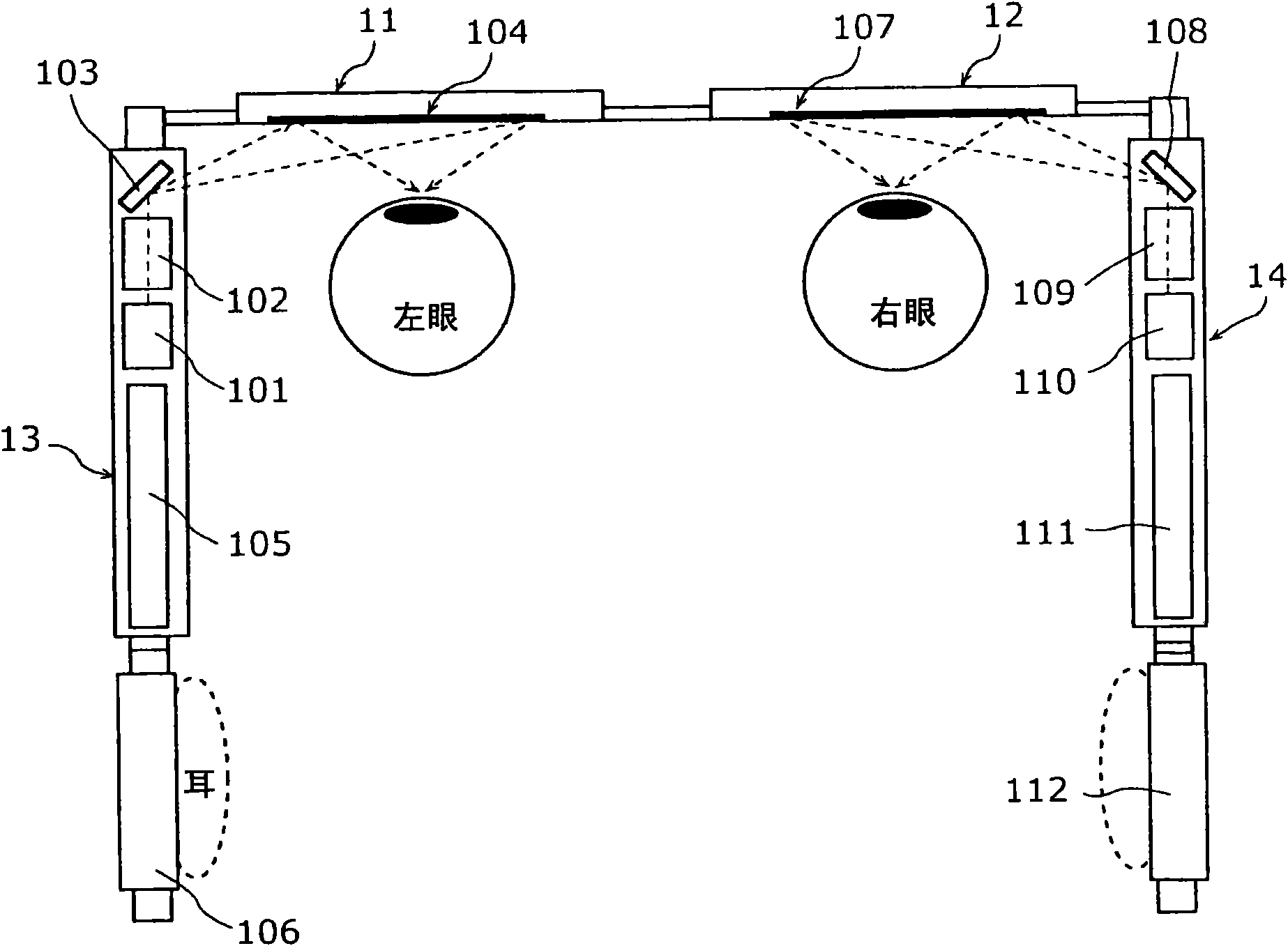
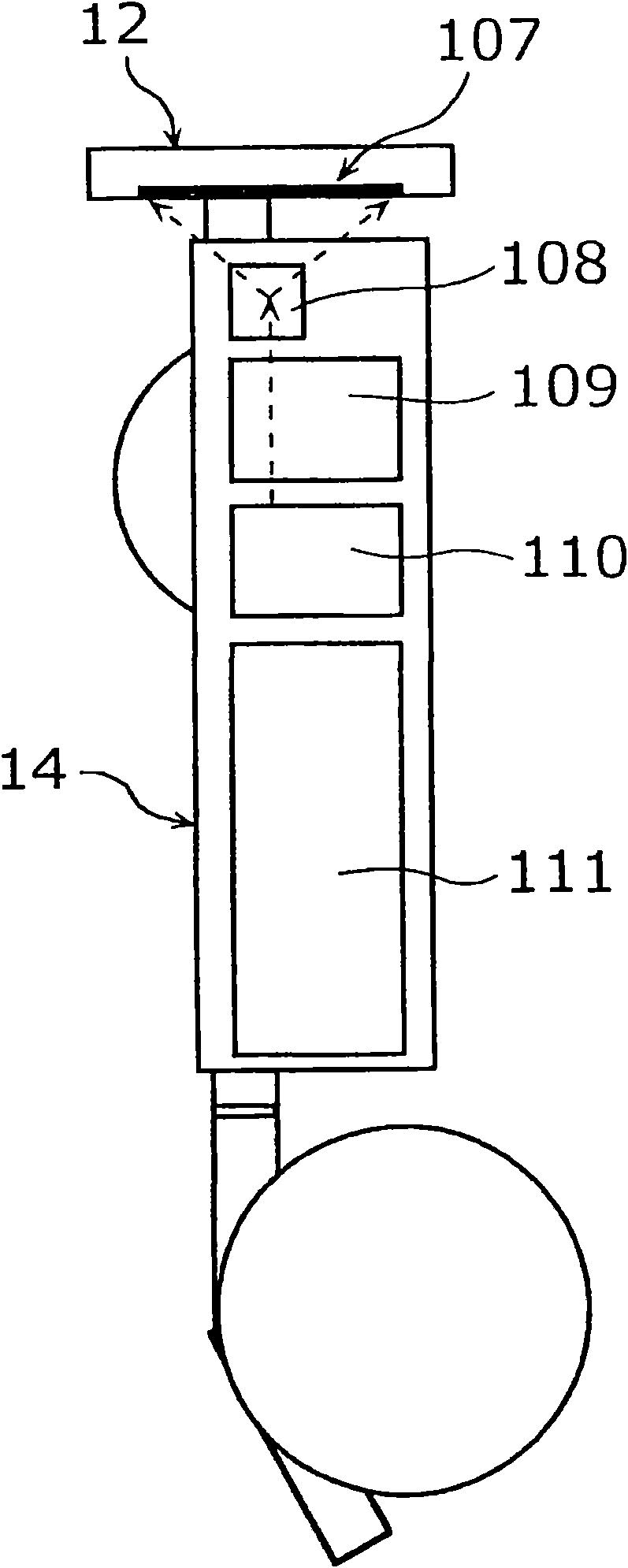
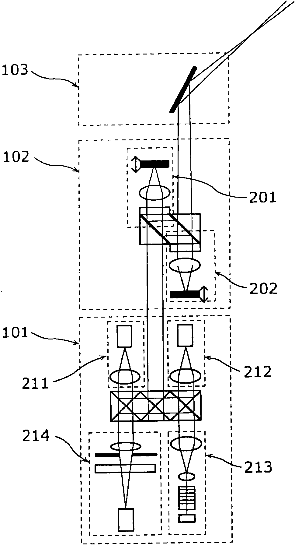
[0261] refer to Figure 1A ~ Figure 3 A glasses-shaped beam scanning display device (head-mounted display: HMD) according to a first embodiment of the present invention will be described. in, Figure 1A is a front view of a beam scanning type display device, Figure 1B is a side view of a beam scanning type display device, figure 2 yes Figure 1A A detailed diagram of part of the image 3 It is a functional block diagram of the beam scanning display device in the first embodiment. The glasses-type beam scanning display device according to the first embodiment of the present invention includes: a display device; a left-eye lens 11 arranged at the position of the user's left eye; a right-eye lens 12 arranged at the position of the user's right eye; Left side mirror leg (temple) 13, its one end is connected to left eye with lens 11, and the other end is fixed on the user's head left side; Right side mirror leg 14, its one end is connected with right eye with lens 12, and the ...

no. 2 Embodiment approach

[0342] In this embodiment, the case where the mirror device structures of the left and right scanning units 103 and 108 in FIG. 1 are different is shown. Hereinafter, the left-eye scanning unit 103 is used as a wide-view scanning unit, and the right-eye scanning unit 108 is used as a narrow-view scanning unit.

[0343] Such as Figure 15 As shown, the left-eye scanning unit 103 used as a wide-view scanning unit is designed to scan at a horizontal angle α2 using incident laser light from the left-eye light source 101. L degrees, vertical scanning angle β2 L degrees and has a display horizontal resolution of Nx2 L , the vertical resolution is Ny2 L image capabilities. In addition, it is assumed that the driving frequency in the horizontal direction of the left-eye scanning unit 103 is Hx2 L , the driving frequency in the vertical direction is Hy2 L , the equivalent resolution per 1 degree scan angle is ΔNx L , ΔNy L . Further, it is assumed that the diameter of the sing...

no. 3 Embodiment approach

[0382] The method shown in the present embodiment is to suppress reduction of the viewing angle during keystone correction by changing the shape of the image displayed for the left and right eyes respectively.

[0383] refer to Figure 1A , Figure 1B , figure 2 with Figure 24 Next, a glasses-type beam scanning display device (head-mounted display: HMD) in a third embodiment of the present invention will be described. in, Figure 1A , Figure 1B , figure 2 The configuration shown in FIG. 1 is the same as that of the first embodiment, and therefore description thereof will be omitted.

[0384] The control units 105 and 111 include integrated circuits for controlling each part of the HMD. The output of laser light emitted from the light sources 101 and 110 and the operations of the wavefront shape changing units 102 and 109 and the scanning units 103 and 103 are controlled by the control units 105 and 111 .

[0385] Figure 24 A functional block diagram of the control ...


PUM


Abstract

An image display device comprises a light source for left eye (101) for outputting an image for left eye that configures a part or all of an original image, a deflection unit for left eye (104) for deflecting the image for left eye outputted by the light source for left eye (101) in direction to a user's left eye, a light source for right eye (110) for outputting an image for right eye that configures a part or all of the original image, a deflection unit for right eye (107) for deflecting the image for right eye outputted by the light source for right eye (110) in direction to a user's right eye, and control units (105, 111) for controlling an image output unit for left eye and an image output unit for right eye so as to output the image for left eye and the image for right eye of which at least one of a position of a pixel, a shape of the image, a size of the image, resolution of the image, and a display frame rate is different from each other so that the user can recognize the original image from the image for left eye and the image for right eye by an image fusion effect.

Description

technical field [0001] The present invention relates to display devices such as HMD (head mount display: head mounted display). Background technique [0002] Currently, display devices such as HMDs (head-mounted displays) use an imaging method (hereinafter referred to as "laser scanning method") that directly scans the retina of the eye two-dimensionally with laser light (for example, refer to Patent Document 1). A display device using a laser scanning method is also called a retinal scanning display (Retinal Scanning Display: RSD), a retinal irradiation display, a retinal light painting display, a laser scanning display, a direct-view display device, and a virtual retinal display (Virtual Retinal Display: VRD). Wait. [0003] Figure 1A with Figure 1B shows a structural example of a glasses-type HMD. exist Figure 1A with Figure 1B In the spectacle frame, light sources 101 and 110 for emitting laser light, wavefront shape changing parts 102 and 109 for controlling the...

Claims


Application Information

Patent Timeline
IPC IPC(8): G02B27/02H04N5/74
Inventor 杉山圭司山本格也黑塚章
Owner PANASONIC CORP
Why Eureka
Try Eureka