Resistance welding equipment and welding control method

A resistance welding and control method technology, applied in resistance welding equipment, welding equipment, welding monitoring devices, etc., can solve problems such as unstable welding quality, achieve the effects of improving quality and stability, ensuring quality, and high visibility

Active Publication Date: 2009-12-02
镇江泛沃新能汽车技术股份有限公司
View PDF0 Cites 42 Cited by
  • Summary
  • Abstract
  • Description
  • Claims
  • Application Information

AI Technical Summary

Problems solved by technology

[0003] The technical problem to be solved by the present invention is to provide a high-precision pressure sensor and tracking system to collect pressure signals and high-precision displacement sensors and tracking systems for the welded workpieces in view of the unstable welding quality of existing resistance welding equipment. Collect displacement signals, run program control through PLC (full name Programmable Logic Controller), and monitor the whole process of welding for metal workpieces, so as to realize the resistance welding equipment and welding with stable welding quality under the online welding conditions of the welded products Control Method

Method used


Image

  • Resistance welding equipment and welding control method
  • Resistance welding equipment and welding control method
  • Resistance welding equipment and welding control method

Examples


Embodiment 1

[0020] Example 1, using resistance welding equipment to weld the wiper motor gear cover

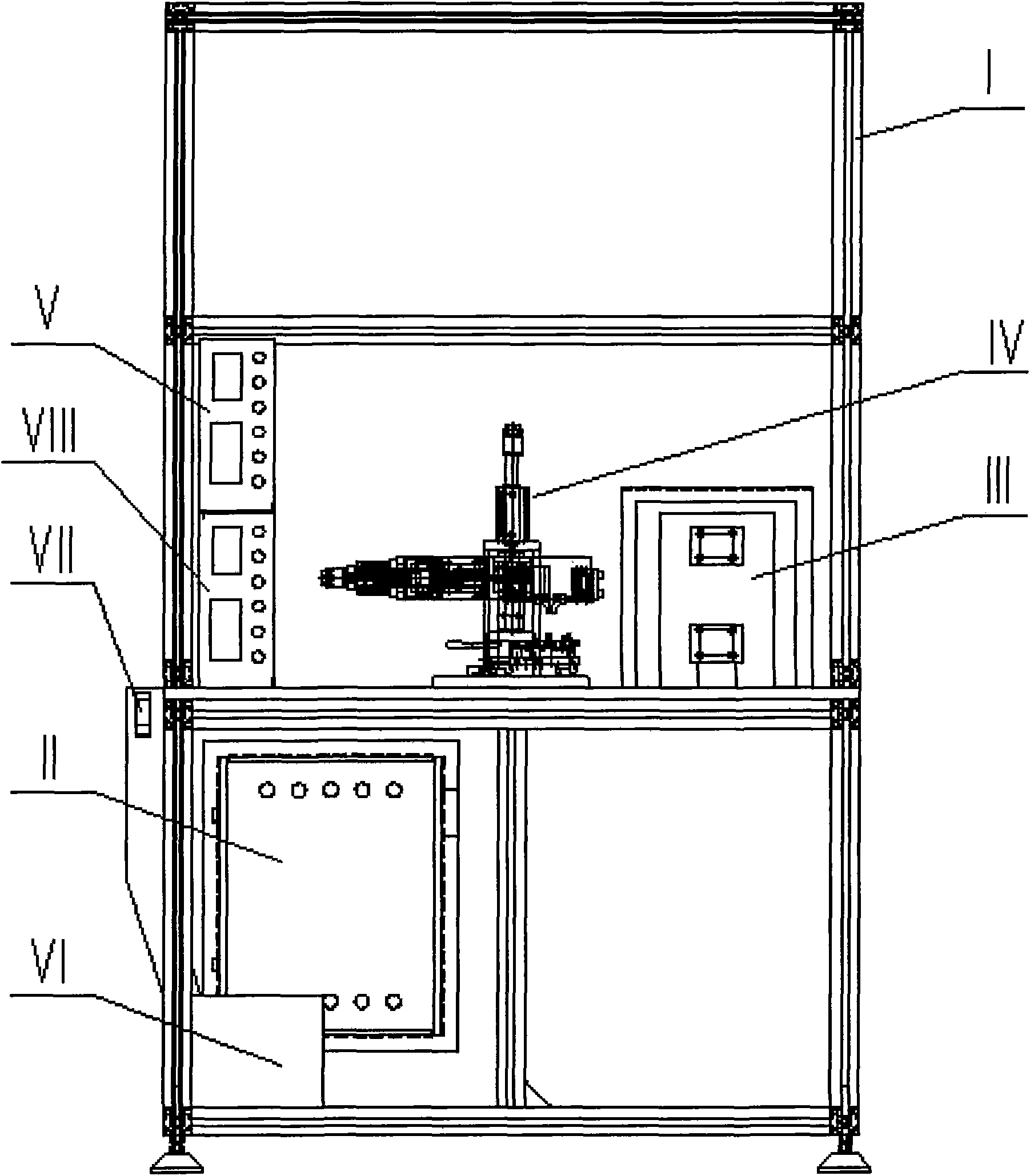
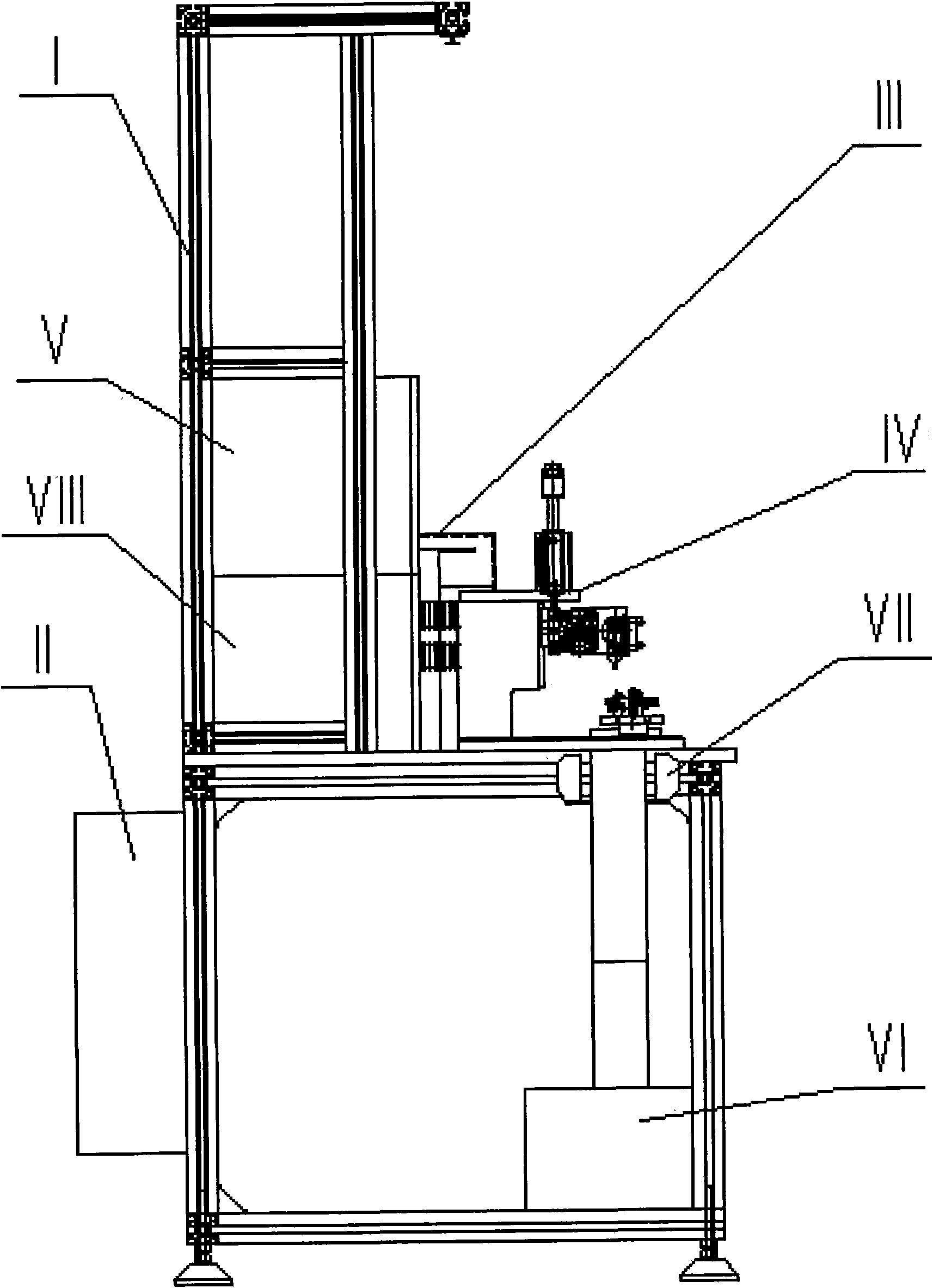
[0021] The resistance welding equipment with the structure of the invention is used to weld the metal insert and the metal spring piece on the gear cover of the automobile windshield wiper system. Referring to the accompanying drawings, the resistance welding equipment is composed of a frame I, an electric control box and a PLC system II, a welding transformer III, an action mechanism IV, a welding machine controller V, a waste box VI, an optical fiber sensor VII and a sensor controller VIII. The box and PLC system II are located at the lower part of the frame I, the welding transformer III is located at the right side of the middle workbench of the frame I, the welding machine controller V and the sensor controller VIII are located at the left side of the middle workbench of the frame I, and the waste box VI One foot is located at the bottom of the frame I, the optical fiber sensor VII i...


PUM


Abstract

The invention provides resistance welding equipment and a welding control method. The resistance welding equipment consists of a frame, an electric cabinet and a PLC system, a welding transformer, an action mechanism, a welder controller, a waste box, an optical fiber sensor and a sensor controller, wherein the action mechanism consists of a baseplate, a main frame, a vertical cylinder, a main linear guide rail, a linear guide rail, a positioning manual press claw, a positioning fixture, a linear bearing, a main linear bearing, a positioning nut, an adjusting pressure spring, a screw mandrel, a servomotor, a coupler, a displacement sensor, a clamping cylinder, a pressure sensor, a left electrode, a right electrode, left and right linear guide rails, left and right linear bearings, an auxiliary frame, a connecting rod and a clamping pressing plate. The pressure sensor and a tracking system are adopted to collect pressure signals, the displacement sensor and the tracking system are adopted to collect displacement signals, and a PLC operational program is adopted for control, so that the welding of metal workpieces adopts dynamic on-line control to comprehensively monitor various welding control points in the whole process, and the welding deformation is controlled between 0.01 and 0.45mm to ensure welding quality.

Description

technical field [0001] The invention relates to welding equipment, in particular to a resistance welding equipment and welding control method for welding small metal objects. Background technique [0002] The existing manual or pneumatically driven resistance welding equipment for welding small metal objects generally controls the welding effect by controlling the welding current and welding time. Since the welding displacement and welding pressure are not kept constant, real-time monitoring cannot be performed at the same time. As a result, there are large quality fluctuations in the welding process, which affects the welding quality of the product. Therefore, the welding performance of the resistance welding equipment for small metal objects still needs to be further improved. Contents of the invention [0003] The technical problem to be solved by the present invention is to provide a high-precision pressure sensor and tracking system to collect pressure signals and hi...

Claims


Application Information

Patent Timeline
Patent Type & Authority Applications(China)
IPC IPC(8): B23K11/00B23K11/25
Inventor 张荣成
Owner 镇江泛沃新能汽车技术股份有限公司
Why Eureka
Try Eureka