
Manufacturing method of thermal head unit, thermal head unit thereof and printer comprising the same

A manufacturing method, thermal head technology, applied in printing and other directions

Active Publication Date: 2009-12-02
BROTHER KOGYO KK
View PDF1 Cites 2 Cited by
  • Summary
  • Abstract
  • Description
  • Claims
  • Application Information

AI Technical Summary

Problems solved by technology

In addition, as a positioning method, conventionally, it has been proposed to perform embossing at a predetermined position of the heat sink and use the embossing to position the thermal head. The process of processing also requires embossing with higher positional accuracy

Method used


Image

  • Manufacturing method of thermal head unit, thermal head unit thereof and printer comprising the same
  • Manufacturing method of thermal head unit, thermal head unit thereof and printer comprising the same
  • Manufacturing method of thermal head unit, thermal head unit thereof and printer comprising the same

Examples


Embodiment Construction

[0031] Hereinafter, an embodiment embodying the present invention will be described in detail with reference to the drawings.

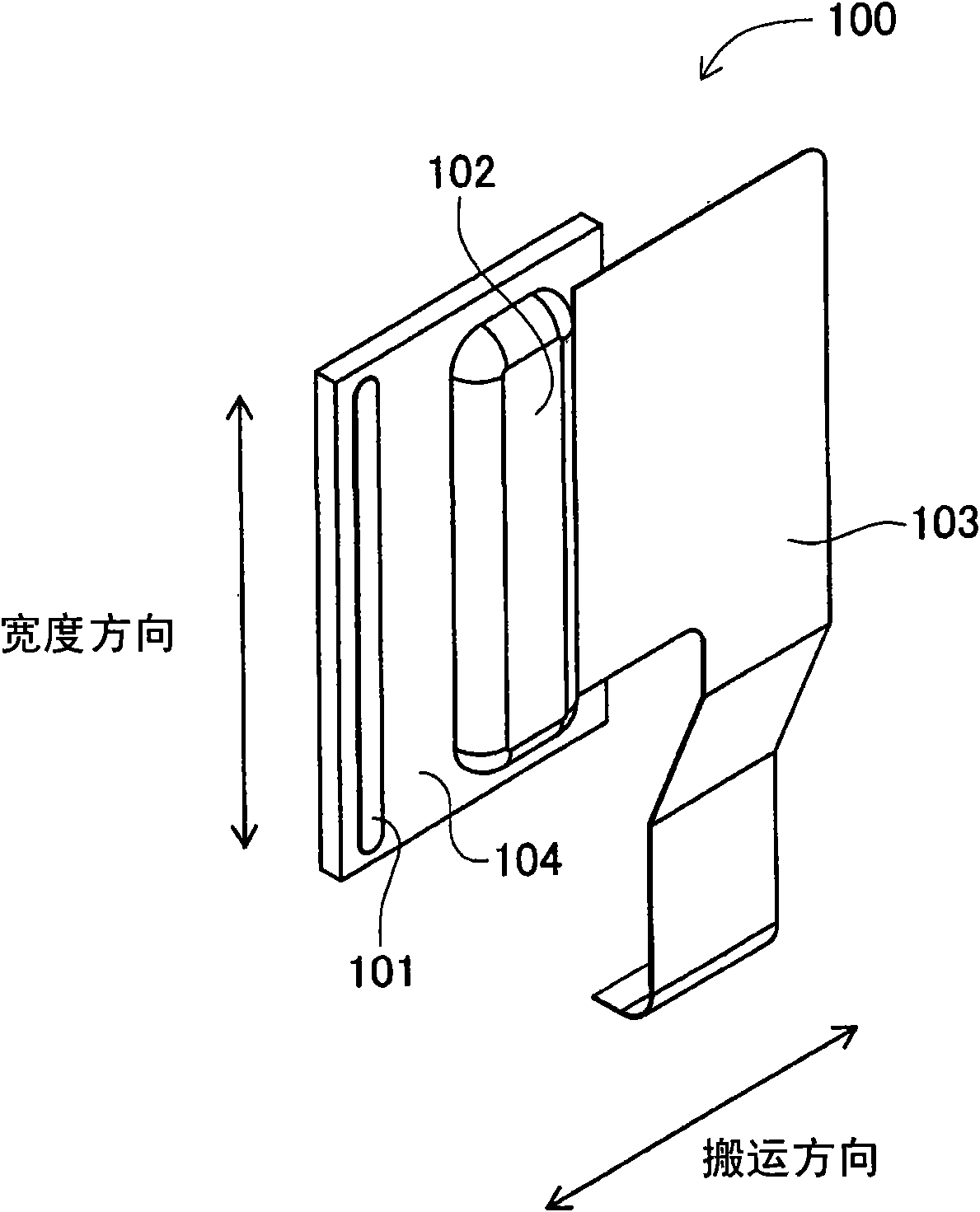
[0032] figure 1 Indicates the thermal head that makes up the thermal head unit. Such as figure 1 As shown, the thermal head 100 is composed of a heating part 101 , a circuit part 102 , a wiring part 103 , and a main body part 104 .

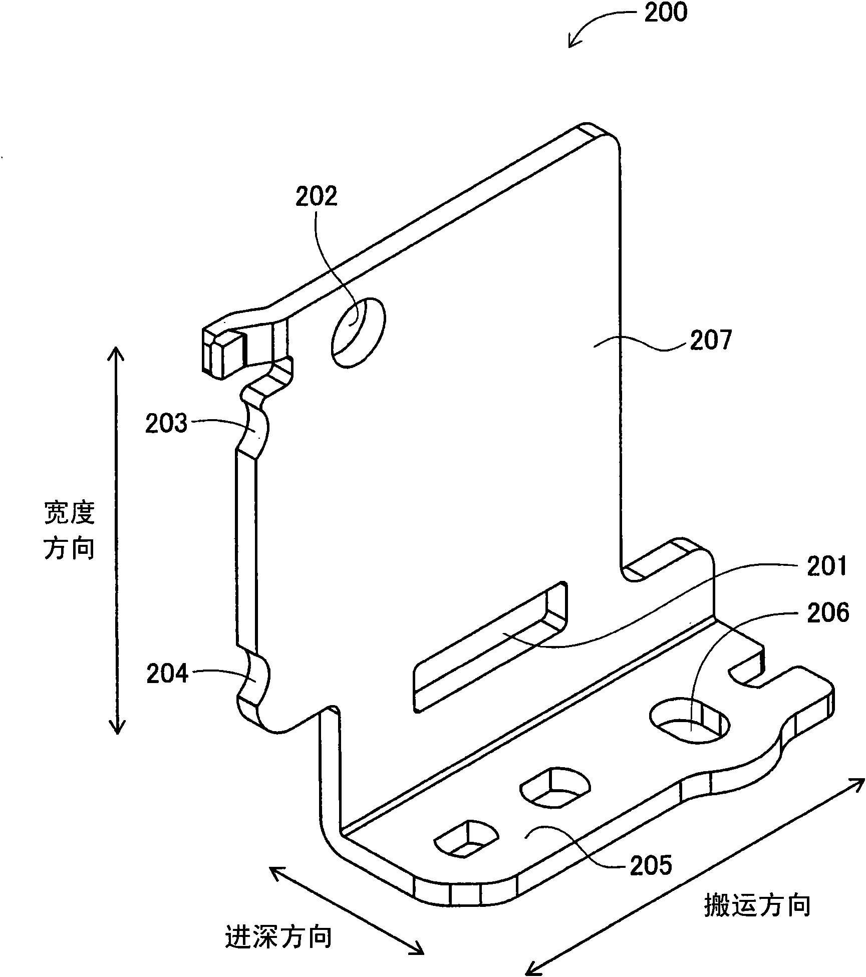
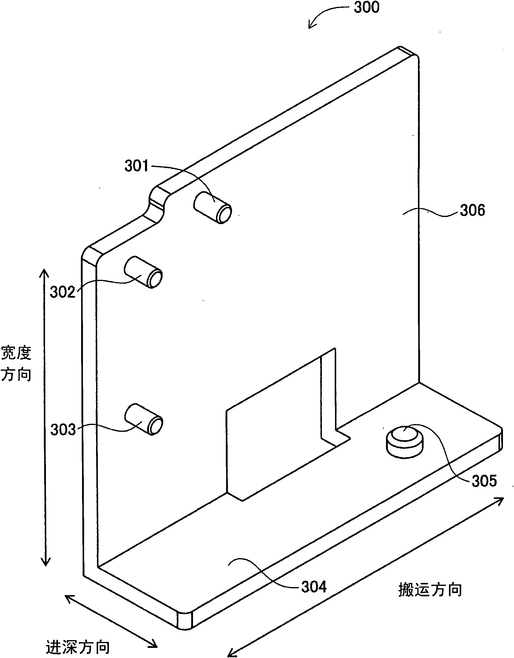
[0033] In addition, the following for convenience, such as Figure 7 As shown, the vertical direction on the paper is referred to as the "width direction", the lower left upper right direction on the paper is referred to as the "transportation direction", and the upper left lower right direction on the paper is referred to as the "depth direction". These directions are derived from placing the thermal head unit U (refer to Figure 12 ) is the width direction and conveying direction of the printing medium when it is assembled on the printing device to print on the printing medium.

[0034] The heat generating unit...


PUM


Abstract

The present invention provides a manufacturing method of a thermal head unit, the thermal head unit thereof and a printer comprising the same. A radiating board (200) is positioned and fixed to a preset position on a clamper (300) through inserting a fourth pin (305) of the clamper (300) through a positioning hole (206) of the radiating board (200). Afterwards, the thermal head (100) is positioned to a preset position of the radiating board (200) fixed to the clamper (300) through contacting the contact part of the thermal head (100) with a first pin (301), a second pin (302) and a third pin (303) of the of the clamper (300). In this state, a clearance is formed between the opposite part of the radiating board (200) opposite to the first pin (301), the second pin (302) and the third pin (303) of the clamper (300) and each pin (301), (302), (303). Additionally, the thermal head (100) is adhibited and fixed to the radiating board (200) through the adhesive (S) coated to the back surface of the thermal head (100) thereby binding the radiating board (200) with the thermal head (100).

Description

technical field [0001] The present invention relates to a thermal head unit used in a printing device. Background technique [0002] Conventionally, various thermal head units including a thermal head and a heat sink have been proposed. Figure 17 Indicates the form of printing using the thermal head unit. The thermal head unit 910 includes a thermal head 911 having a heat generating portion 912 and a heat sink 913 for dissipating heat from the heat generating portion 912 . In addition, when the medium to be heated 915 (ribbon, thermal paper) passes between the thermal head 911 and the platen 914 , heat is generated by the heating elements of the heating unit 912 in a heated state. As a result, the ribbon is melted or the heat-sensitive material layer is colored, so that printing can be performed at a predetermined position on the printing medium. [0003] Figure 18 It is a figure which looked at the thermal head unit 910 from the platen 914 side. Such as Figure 18 As...

Claims


Application Information

Patent Timeline
Patent Type & Authority Applications(China)
IPC IPC(8): B41J2/335B41J2/32
Inventor 佐郷朗
Owner BROTHER KOGYO KK
Learn More