
Communication equipment suspension device applied to vehicle

A technology for transportation and communication equipment, applied in mechanical equipment, transportation and packaging, springs/shock absorbers, etc., can solve the problems of vibration, damage, and bumping of the satellite navigation device 1, and achieve the improvement of industrial efficiency, simple structure, low cost effect

Inactive Publication Date: 2009-12-09
MITAC COMP (SHUN DE) LTD
View PDF0 Cites 12 Cited by
  • Summary
  • Abstract
  • Description
  • Claims
  • Application Information

AI Technical Summary

Problems solved by technology

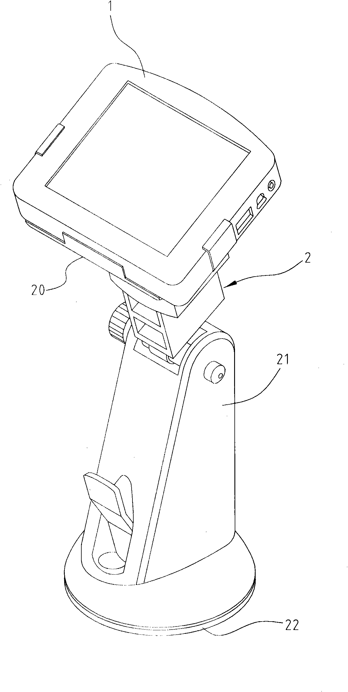
[0004] However, there are many deficiencies in the existing fixed foot stand 2. Specifically, when the car is running, it is very easy to shake due to uneven conditions on the ground, and the fixed foot stand 2 is not equipped with any anti-vibration devices, so it will inevitably Cause the satellite navigation device 1 to vibrate accordingly, and affect the normal use of the satellite navigation device 1
In addition, it is also possible that the satellite navigation device 1 collides with other parts due to violent shaking, resulting in damage
Furthermore, since the satellite navigation device 1 is adsorbed on the windshield, it may also affect the consideration of driving safety.

Method used


Image

  • Communication equipment suspension device applied to vehicle
  • Communication equipment suspension device applied to vehicle
  • Communication equipment suspension device applied to vehicle

Examples


no. 1 example

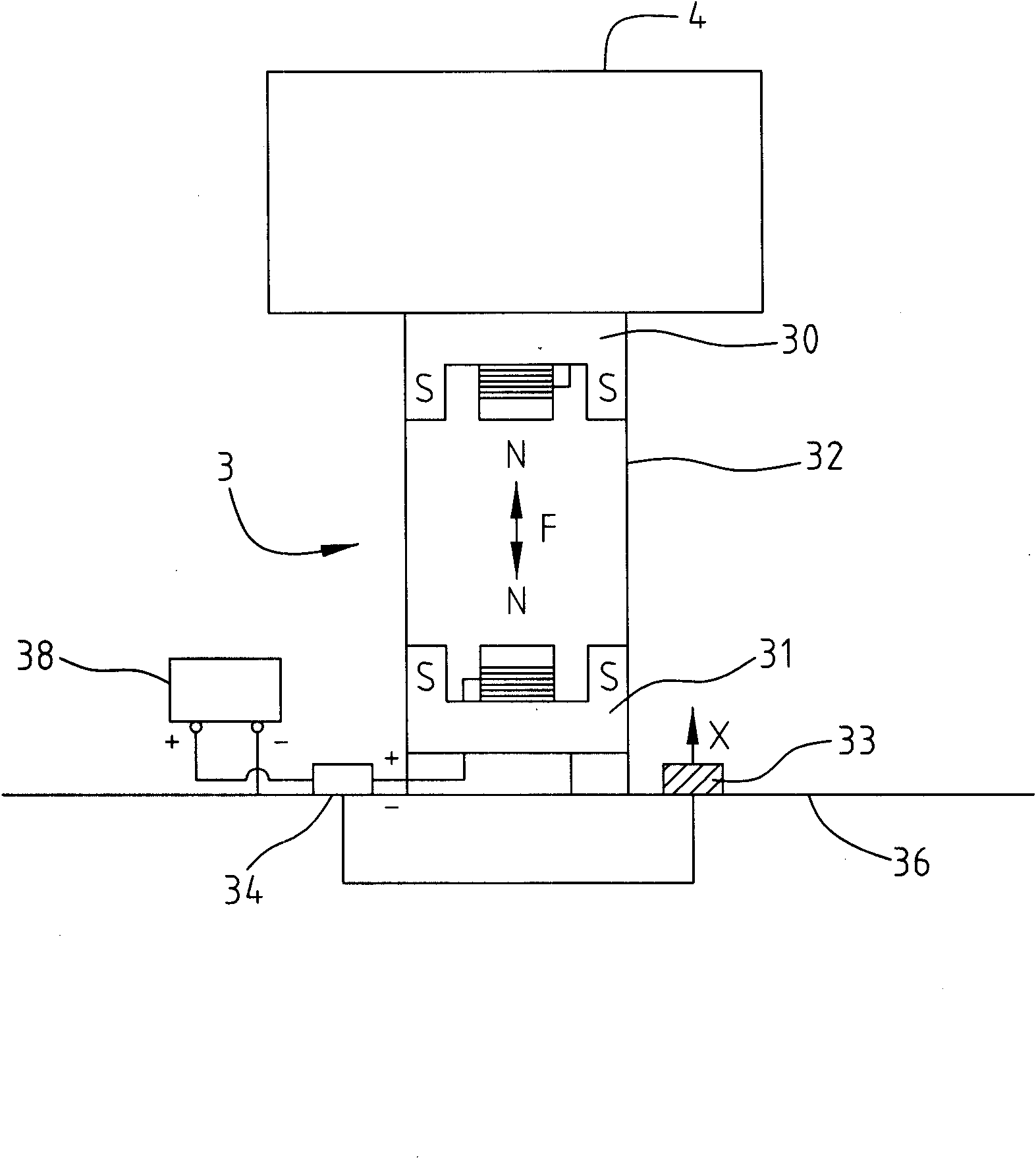
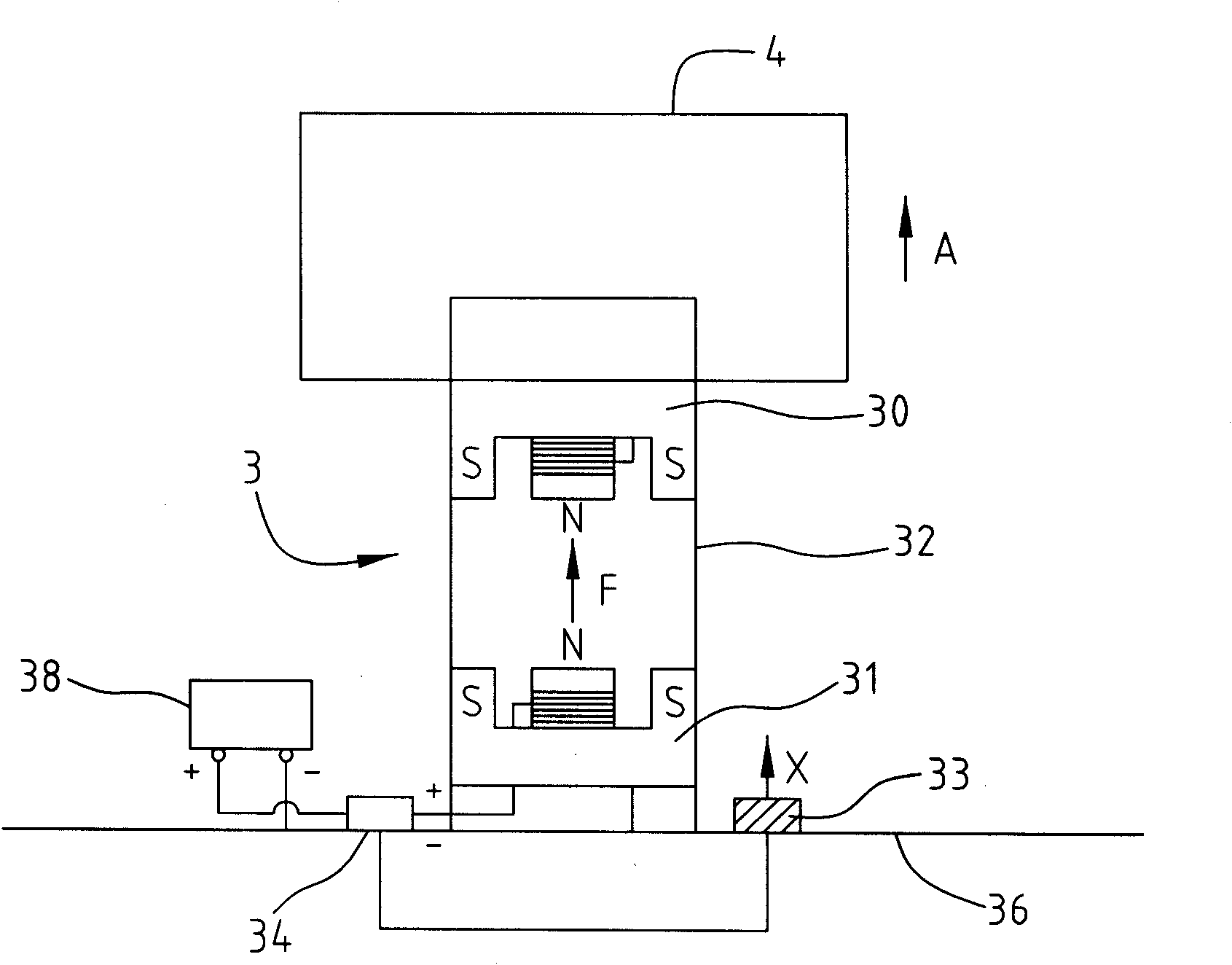
[0019] see figure 2 , which is the first embodiment of the communication equipment shock absorber 3 (hereinafter referred to as the communication equipment shock absorber 3) applied to the vehicle of the present invention. In this embodiment, the communication equipment 4 (hereinafter referred to as the communication equipment shock absorber 3) applied to the vehicle Said communication equipment 4) refers to the satellite navigation device for vehicles. Of course, in actual conditions, it can be other portable electronic devices such as mobile phones, personal digital assistants (PDAs), etc., and is not limited to this embodiment. In this embodiment, the shock-absorbing device 3 for communication equipment is applied to automobiles, more specifically, it is installed on the body 36 of the automobile. In other embodiments of the present invention, the shock-absorbing device 3 for communication equipment can also be applied to ships or Aircraft and other means of transportation...

no. 2 example

[0032] see Figure 5 and Figure 6 , which are schematic diagrams of two different embodiments of the second embodiment of the communication equipment shock absorber 3' applied to vehicles (hereinafter referred to as the communication equipment shock absorber 3') of the present invention.

[0033] In the first embodiment, the shock-absorbing device 3 of the communication equipment is used for shock-absorbing the communication equipment 4 in the vertical direction, but the difference of this embodiment is that the communication equipment 4' is shock-absorbed in the horizontal direction.

[0034] Such as Figure 5 As shown, in this embodiment, the communication device 4' and one end of the connecting rod 37' are fixed to each other by, for example, snapping or pasting. The other end of the rod 37' is connected and fixed to the first magnet 30', and the first magnet 30' is combined with the limiter 32' in a sliding manner, so that the first magnet 30' can only move bidirectiona...


PUM


Abstract

The invention discloses a communication equipment suspension device applied to a vehicle, which detects the position change of communication equipment mainly by a distance detecting unit and then adjusts the magnetism of a first magnet fixedly arranged at the communication equipment or a second magnet arranged at a vehicle by an electromagnetic control unit, wherein the first magnet is opposite to the second magnet at the same polar ends so as to enable the communication equipment to be returned to the initial position without position change, thereby achieving the effect of suspension.

Description

【Technical field】 [0001] The invention relates to a shock absorber for communication equipment, in particular to a shock absorber for communication equipment used in vehicles. 【Background technique】 [0002] In today's era of increasingly convenient transportation, the scope of human activities is gradually expanding, and in order to save time and improve efficiency, it is necessary to accurately locate the position of people or objects in a wide area, and at the same time have a device that can communicate anytime and anywhere to reduce The waste of manpower, time and resources is quite urgent, so the integration of satellite navigation devices (GPS) into mobile communication tools such as mobile phones has become quite popular. [0003] At present, handheld or portable satellite navigation products are very popular in the market. Almost every car is equipped with a satellite navigation device. Usually, the fixed structure of the existing satellite navigation device used in...

Claims


Application Information

Patent Timeline
Patent Type & Authority Applications(China)
IPC IPC(8): F16F6/00F16F15/03B60R11/02
Inventor 郑郁锜
Owner MITAC COMP (SHUN DE) LTD
Learn More