
Stress equation solver applying Mohr circle calculation method

A calculation method, solver technology, applied in the direction of calculation, computer, digital computer parts, etc.

Inactive Publication Date: 2011-05-25
HARBIN INST OF TECH
View PDF3 Cites 0 Cited by
  • Summary
  • Abstract
  • Description
  • Claims
  • Application Information

AI Technical Summary

Problems solved by technology

Among the existing devices, there is no device that can calculate the stress from the Mohr circle that is convenient to carry
And because engineers will often work in various environments, the huge and cumbersome tools on the market have brought them troubles to carry.

Method used


Image

  • Stress equation solver applying Mohr circle calculation method
  • Stress equation solver applying Mohr circle calculation method
  • Stress equation solver applying Mohr circle calculation method

Examples


specific Embodiment approach 1

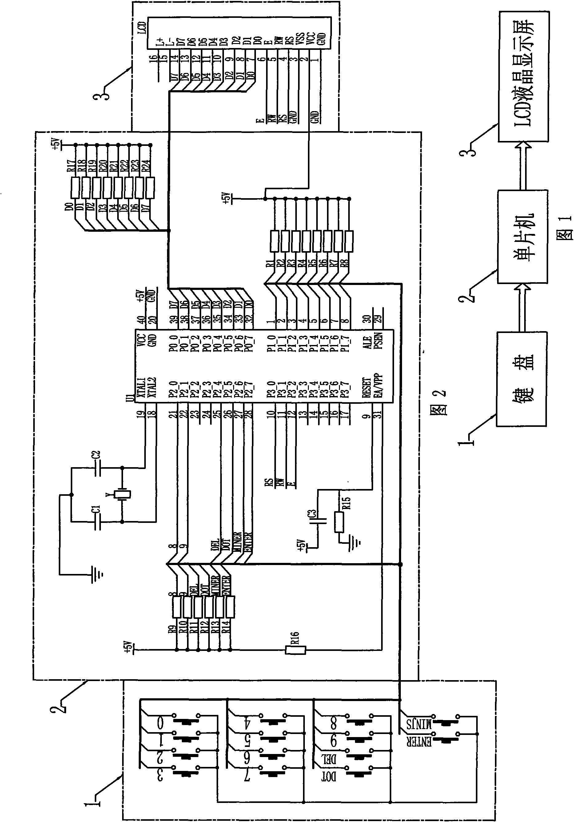
[0024] Specific implementation mode one: combine figure 1 Describe the present embodiment, present embodiment comprises keyboard 1, single-chip microcomputer circuit 2 and LCD liquid crystal display screen 3, the signal output end of keyboard 1 is connected the signal input end of single-chip microcomputer circuit 2 by keyboard data bus, the signal output end of single-chip microcomputer circuit 2 passes display The data bus is connected to the signal input terminal of the LCD liquid crystal display 3, and the data result is displayed through the LCD liquid crystal display 3.

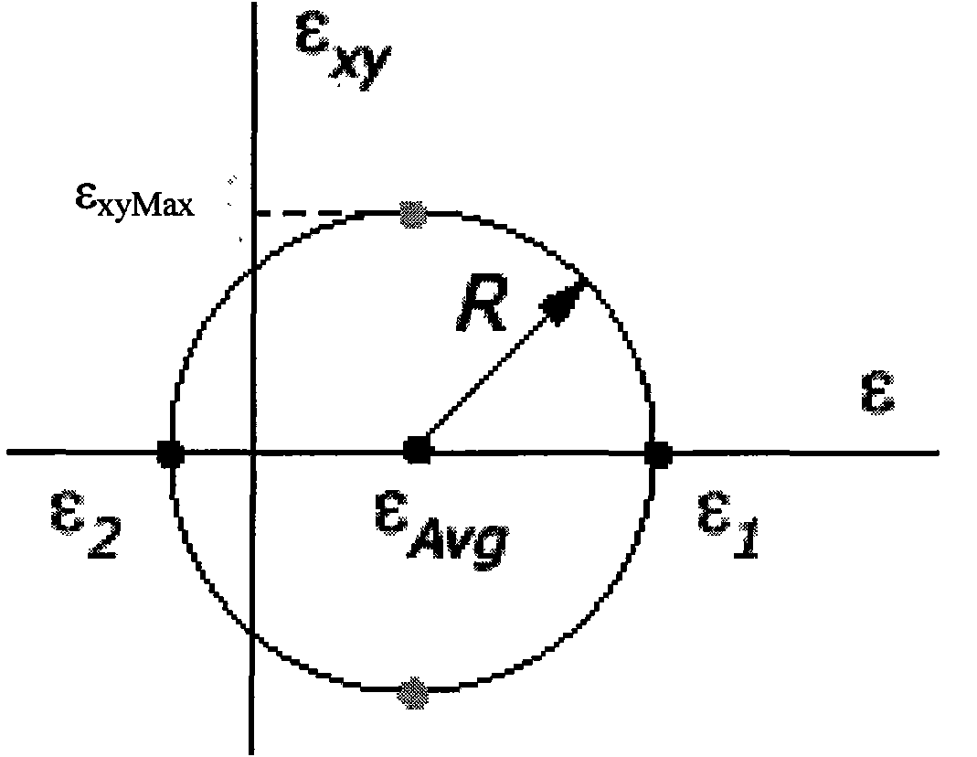
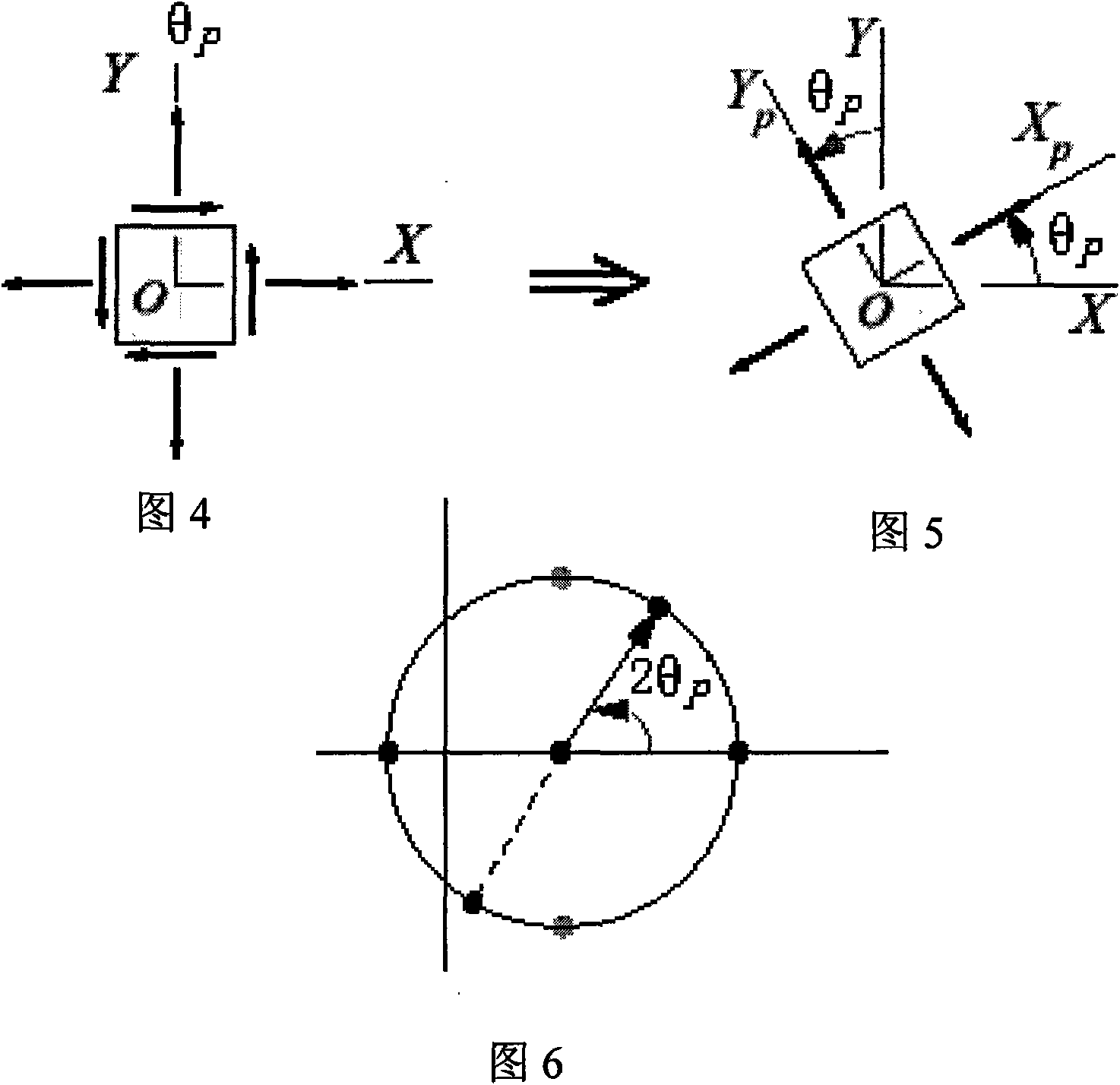
[0025] according to Figure 3 to Figure 6 Explain that the working process of the device in the present embodiment is:

[0026] When using the calculation of the stress circle, the required parameters are the corresponding point of the stress in the coordinate system and the circle determined by it. Through the calculation of this circle, the maximum stress to be borne by a component and the stress in...

specific Embodiment approach 2

[0030] Specific implementation mode two: combination figure 2 Illustrate this embodiment, the difference between this embodiment and specific embodiment one is that single-chip microcomputer circuit 2 adopts AT89C51 chip, and described AT89C51 chip is chip U1,

[0031] The single-chip microcomputer circuit 2 is composed of a chip U1, a crystal oscillator Y, a first resistor R1 to a twenty-fourth resistor R24, and a first capacitor C1 to a third capacitor C3;

[0032] The pins 1 to 8 of the chip U1 are respectively connected to one end of the first resistor R1 to the eighth resistor R8 in turn; the other ends of the first resistor R1 to the eighth resistor R8 are connected to +5V voltage at the same time;

[0033] The pin 9 of the chip U1 is connected to one end of the third capacitor C3 and one end of the fifteenth resistor R15 at the same time, the other end of the third capacitor C3 is connected to +5V voltage, and the other end of the fifteenth resistor R15 is connected to...


PUM


Abstract

The invention provides a stress equation solver applying Mohr circle calculation method and relates to the fields of engineering mechanics and electron technology, in particular to a method utilizing electronic equipment as an auxiliary tool to complete calculation required for stress in engineering. In order to more conveniently and rapidly calculate a stress state, the invention adopts the following structure that the invention comprises a keyboard (1), a single chip circuit (2) and a liquid crystal display (LCD) (3), wherein the signal output end of the keyboard (1) is connected with the signal input end of the single chip circuit (2) by a keyboard data bus, and the signal output end of the single chip circuit (2) is connected with the signal input end of the LCD (3) by a display data bus. The invention adopts the single chip circuit (2), applies a Mohr circle in changing the calculation of the stress into a single chip program and solves the defect that an arithmetic device is complicated. The invention has broad market prospect and strong practicability, can fast and accurately calculate the internal stress state of each component for engineering technical personnel and also can be used as a teaching auxiliary tool for material mechanics. In addition, the advantages of convenience and fastness are very outstanding.

Description

technical field [0001] The invention relates to the fields of engineering mechanics and electronic technology, in particular to using electronic equipment as an auxiliary tool to complete the calculation of stress required in engineering. Background technique [0002] In various engineering practices, although the types and uses of components are different, when the structure works normally, each component is subject to external forces transmitted from adjacent components or other objects. In order to ensure the normal operation of components, three requirements generally need to be met. [0003] First of all, the components have sufficient strength, and the components must not break under a certain external force. For example, when lifting heavy objects, the steel wire rope should not be broken by the heavy objects. Secondly, some components, such as the machine tool spindle, have excessive permanent deformation after being stressed, and the deformation of the machine cann...

Claims


Application Information

Patent Timeline
Patent Type & Authority Patents(China)
IPC IPC(8): G06F15/02
Inventor 许诺魏红江张玉瑶孔芳园尹松乔高寒松位寅生
Owner HARBIN INST OF TECH
Learn More