Key lifting switch device and assembling fixture and assembling technology thereof

A technology for lifting switches and assembling fixtures, which is applied in the direction of electric switches, electrical components, circuits, etc. It can solve the problems of affecting production efficiency, inconvenient installation, and difficult realization of fixture accuracy, and achieves improved assembly efficiency, reduced complexity, and excellent assembly. The effect of precision

Active Publication Date: 2009-12-09
G TECH TECH
View PDF2 Cites 19 Cited by
  • Summary
  • Abstract
  • Description
  • Claims
  • Application Information

AI Technical Summary

Problems solved by technology

[0003] The biggest deficiency of this structure of CN2366889Y lies in the resulting assembly process, the assembly between its first frame and the second frame, the assembly of the first frame and the second frame and the keycap and positioning plate, and the overall Assembling the structure, etc., due to the cooperation of multiple tiny holes and pivots, it is not convenient to realize streamlined production, thus affecting production efficiency
It is this limitation that causes the technical solutions of the two patents cited in the present invention to be unable to overcome the defects of the assembly process
The defect of CN2366889Y has been analyzed before, and the defect of CN1716483A is also obvious. In addition to the inconvenience of installing the sliding end of the connecting rod part on the positioning plate, the more important thing is the assembly of the toothed meshing relationship of the connecting rod part. It is often difficult to perfectly cooperate with each other, resulting in a low yield of finished products
[0007] In addition, the connecting rod part of CN1716483A patent announcement is not easy to be injection-molded in the meshing shape during use, but must exist in the injection mold at a distance, and must be manually repositioned on the positioning plate and the k

Method used


Image

  • Key lifting switch device and assembling fixture and assembling technology thereof
  • Key lifting switch device and assembling fixture and assembling technology thereof
  • Key lifting switch device and assembling fixture and assembling technology thereof

Examples


Example Embodiment

[0054] Below in conjunction with accompanying drawing and embodiment, the present invention will be further described:
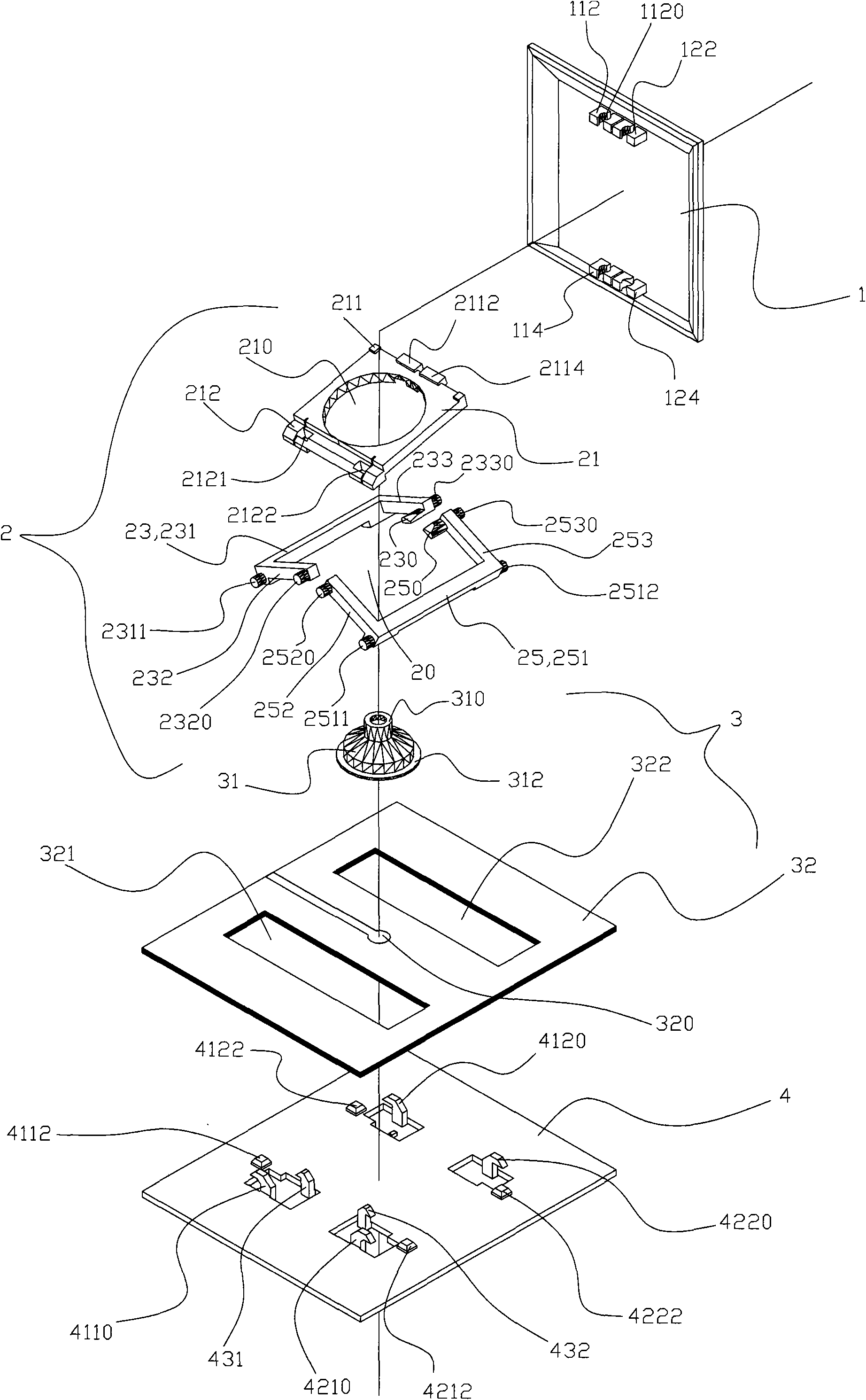
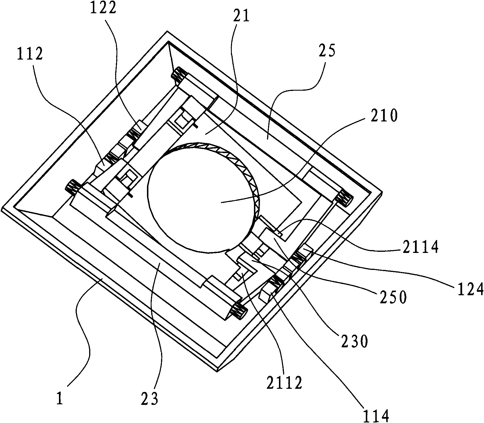
[0055] see figure 1 As shown, the key lift switch device of the present invention is composed of a key cap 1 , a telescopic assembly 2 , a switch mechanism 3 and a support plate 4 . The main improvements of the key lift switch device of the present invention will be disclosed as follows: the telescopic assembly 2 and some components on the bottom surface of the keycap 1 and the upper surface of the support plate 4 related to the improvement of the telescopic assembly 2 .

[0056] Please understand the specific structure of the telescopic assembly 2 of the present invention:
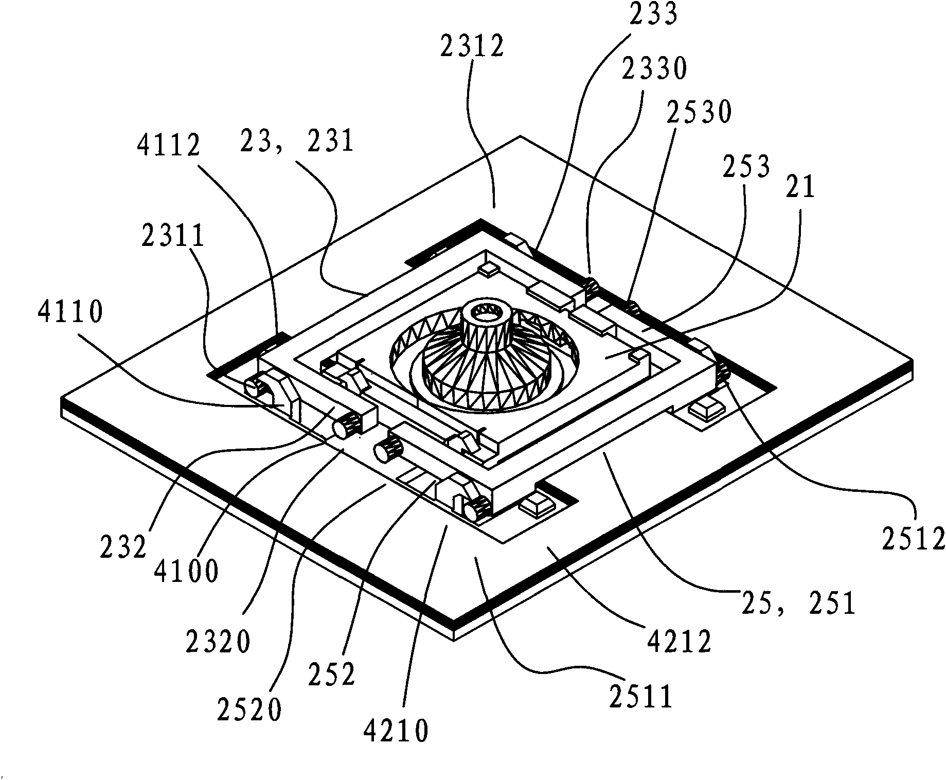
[0057] combine figure 1 and figure 2 , The telescopic assembly 2 of the present invention includes a pair of U-shaped frames 23 and 25 with a symmetrical structure and a plate-shaped synchronizing slide 21 .

[0058] The U-shaped frames 23, 25, including figure 1 The first frame 2...


PUM


Abstract

The invention discloses a key lifting switch device, comprising a keycap, a retractable assembly positioned above a base plate, a switch mechanism for closing and opening the key signal corresponding to the keycap lifting action, the retractable assembly comprises a pair of frames which are impossible to contact with each other, are arranged in a reciprocal manner and form a cavity, the corresponding bottom edges of the two frames can be arranged in two sliding kits which are preset at the two sides of the base plate in a sliding manner, the respective corresponding top parts thereof are arranged with two pivoting-arranged kits which are preset on the bottom of the keycap in a pivoting manner; synchronous sliding pieces used for pressing the synchronous lifting of the pair of frames penetrates the cavity of the pair of the frames, one side thereof is arranged on the base plate and the other side thereof is limited to move along with the retractable movement of the bottom surface of the keycap. In addition, the invention also discloses an assembling fixture and an assembling technology corresponding to the switch device. Compared with the prior art, in the invention, the structure of the key lifting switch device is simplified, the assembling fixture and the assembling technology are improved, thus the production efficiency of keyboards and the finished product acceptability are further improved.

Description

【Technical field】 [0001] The present invention relates to a key lift switch device for a keyboard, in particular to a key lift switch device for an ultra-thin key in a keyboard as an input device of an electronic instrument, and also to an automatic assembly method for a key corresponding to the one-key lift switch device. 【Background technique】 [0002] Jingyuan Computer Co., Ltd., an applicant from Taiwan Province of China, applied in China with the subject of "ultra-thin keyboard keys", which was announced on March 1, 2000, with the announcement number CN2366889Y. This patent represents the mainstream structure of early ultra-thin keyboard keys, which is widely used in keyboards of various notebook computers and is welcomed to a certain extent. Please refer to the instruction manual of the announcement for its structure, which mainly includes keycap, positioning plate, first frame, second frame, elastic body, thin film circuit board and bottom plate. part and several pos...

Claims


Application Information

Patent Timeline
IPC IPC(8): H01H13/52H01H13/20H01H13/705H01H3/12H01H11/00
CPCH01H3/122H01H11/00
Inventor 黎柏松
Owner G TECH TECH
Why Eureka
Try Eureka