Hollow steel girder and steel framework system

A technology of steel beam and hollow, applied in the direction of joists, girders, trusses, etc., can solve the problems of high beam height and cumbersome processing, and achieve the effect of reducing height, good application prospect and expanding effective use of floor height.

Active Publication Date: 2009-12-16
CE CENT FOR ENG RES TEST & APPRAISAL
View PDF1 Cites 15 Cited by
  • Summary
  • Abstract
  • Description
  • Claims
  • Application Information

AI Technical Summary

Problems solved by technology

Although the honeycomb beam has the advantage of being easy to pass through the pipeline, the disadvantage is that the height of the beam is still high, and the processing is more cumbersome

Method used


Image

  • Hollow steel girder and steel framework system
  • Hollow steel girder and steel framework system
  • Hollow steel girder and steel framework system

Examples


Embodiment 1

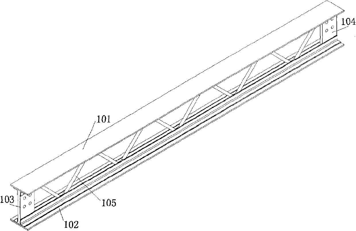
[0072] The hollow steel beam provided by Embodiment 1 of the present invention is as follows: Figure 1A , Figure 1B and Figure 1C shown.

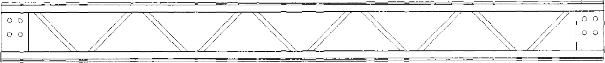
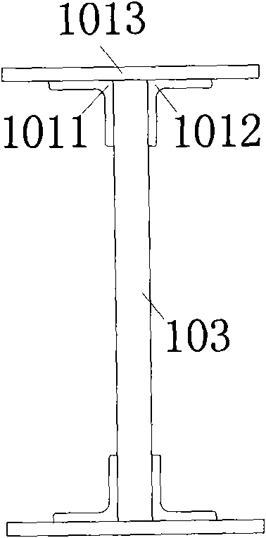
[0073] Figure 1A It is the southwest axial side view of the hollow steel beam provided by Embodiment 1 of the present invention, Figure 1B is its corresponding front view, Figure 1C is its left view.

[0074] From Figure 1A It can be seen that the hollow steel girder includes: an upper flange 101, a lower flange 102, an end gusset plate 103 at the left end of the steel girder, and an end gusset plate 104 at the right end of the steel girder, and at least one row arranged on the upper flange 101 , the lower flange 102, and the web 105 between the end gussets 103 and 104.

[0075] Wherein, each end gusset plate is composed of a single steel plate, and the end gusset plate is parallel to the longitudinal axis of the upper and lower flanges.

[0076] Such as Figure 1C As shown, the upper flange 101 and the lower flange 102 have th...

Embodiment 2

[0083] The hollow steel beam provided by the second embodiment of the present invention is as follows: Figures 2A-2C shown.

[0084] Figure 2A It is the southwest axial side view of the hollow steel beam provided by the second embodiment of the present invention, Figure 2B is its corresponding front view, Figure 2C is its left view.

[0085] Figure 2A-Figure 2C Vierendeel beams shown, with Figure 1A-Figure 1C The hollow steel girders shown are similar, the difference is that the webs are in double rows (marked as 201 and 202 in the figure), and each row of webs is composed of a whole round steel bent into a W shape, from Figure 2C It can be clearly seen that the tops of the two rows of webs 201 and 202 are respectively connected with the two angle steels 2031 and 2032 in the upper flange, and the bottoms of the two rows of webs 201 and 202 are respectively connected with the two angle steels in the lower flange 2041 and 2042 connections.

Embodiment 3

[0087] The hollow steel beam provided by Embodiment 3 of the present invention is as follows: Figures 3A-3C shown.

[0088] Figure 3A It is the southwest axial side view of the hollow steel beam provided by Embodiment 3 of the present invention, Figure 3B is its corresponding front view, Figure 3C is its left view.

[0089] The hollow steel girder provided by the third embodiment of the present invention is similar in structure to the hollow steel beam provided by the first embodiment, the difference is that at least one oblique web member is provided between the end gusset plate and the web member. From Figure 3A It can be seen from the figure that a diagonal web bar 303 is arranged between the end gusset plate 301 and the web bar 302 , and a diagonal web bar 305 is arranged between the end gusset plate 304 and the web bar 302 .

[0090] The function of the diagonal web can strengthen the strength of the node area of ​​the hollow steel beam.


PUM


Abstract

The invention discloses a hollow steel girder, which comprises a top flange, a bottom flange, at least one row of web members and two end part gusset plates, wherein the end part gusset plates are arranged at two ends of the top flange and the bottom flange, and are respectively connected with the top flange and the bottom flange; and the web members have a truss structure, and are arranged between the top and bottom flanges and the end part gusset plates. Spaces facilitating the passing of pipelines are formed between the top and bottom flanges and the web members with the truss structure, advantages of the truss structure and a solid girder are comprehensively applied, the height of the steel girder is reduced to the utmost, and the effective using floor height of a building is enlarged as possible; and components of the hollow steel girder have good structural performance, and the hollow steel girder can meet requirement of civil and residential buildings on floor height, and has wide applicable range and good application prospect.

Description

technical field [0001] The invention relates to the field of construction engineering, in particular to a hollow steel beam and steel frame system. Background technique [0002] For civil steel structure buildings, especially high-rise steel structure buildings, due to the limitation of storey height, the height of the steel beam section is greatly restricted. At the same time, in the design of various pipelines in high-rise steel structure buildings, it is also necessary to Arranged within the range of the structural beam height to further increase the actual use height of the house and achieve the purpose of reducing the overall floor height. [0003] In order to reduce the beam height and facilitate the crossing of various pipelines, many scholars have proposed new solutions, such as the patent application number 200480032009, which proposes to bend the thin steel plate into a T shape, and insert the web plate into the upper and lower T-shaped flange plates It is connect...

Claims


Application Information

Patent Timeline
Patent Type & Authority Applications(China)
IPC IPC(8): E04C3/08E04B1/19
Inventor 娄宇黄健
Owner CE CENT FOR ENG RES TEST & APPRAISAL
Why Eureka
Try Eureka