Inferior coal micro-oil ignition combustor

A micro-oil ignition, oil burner technology, applied in burners, burners burning powder fuel, combustion ignition and other directions, can solve the problems of excess oxygen in low temperature areas, no cooling measures, large blocked flow area, etc. The effect of high ember rate, good environmental protection effect and long service life

Inactive Publication Date: 2009-12-16
范昌 +2
View PDF5 Cites 7 Cited by
  • Summary
  • Abstract
  • Description
  • Claims
  • Application Information

AI Technical Summary

Problems solved by technology

The pulverized coal concentrator of this burner cannot eliminate the vortex area behind it, which greatly increases the velocity of the wind powder entering the primary pulverized coal combustion chamber, which is very unfavorable for ignition
As another example, the separation ring used in Chinese Patent Publication No. CN101329064A and Application No. 200810064783.4 not only produces a recirculation zone thereafter, but also has a relatively large blocked flow area, which increases the resistance loss of the burner and not only causes serious damage to the burner. Wear and tear will also affect the original design of the boiler aerodynamic field and change the original performance of the boiler
[0005] Chinese patent ZL03255982.8 adopted a single-side oil gun heating method, which cannot form a rotating flame; although the disclosed patent of Chinese patent CN101135445A has adopted a double-side oil gun arrangement, it does not form a tangential rotary combustion. In the powder combustion chamber, the situation of "oxygen deficiency in the high temperature area and excess oxygen in the low temperature area" was caused
[0006] Although the Chinese patent CN 201093529Y also installed a blunt body in the burner, there is no cooling measure, which makes it unable to work normally in practice, and it has a great impact on the flow area of ​​the burner, which will inevitably change the original performance of the burner. and cause severe wear and tear

Method used


Image

  • Inferior coal micro-oil ignition combustor
  • Inferior coal micro-oil ignition combustor
  • Inferior coal micro-oil ignition combustor

Examples


Embodiment

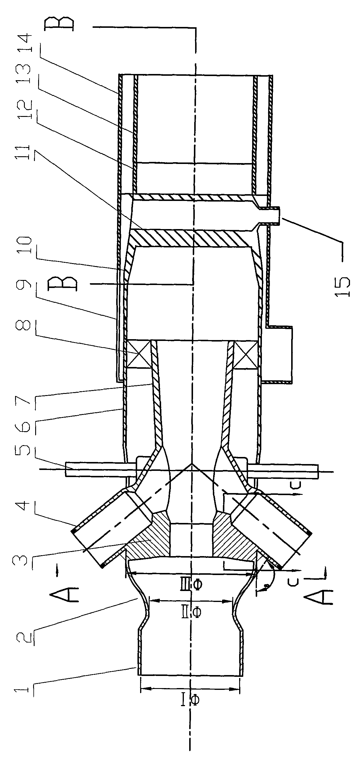
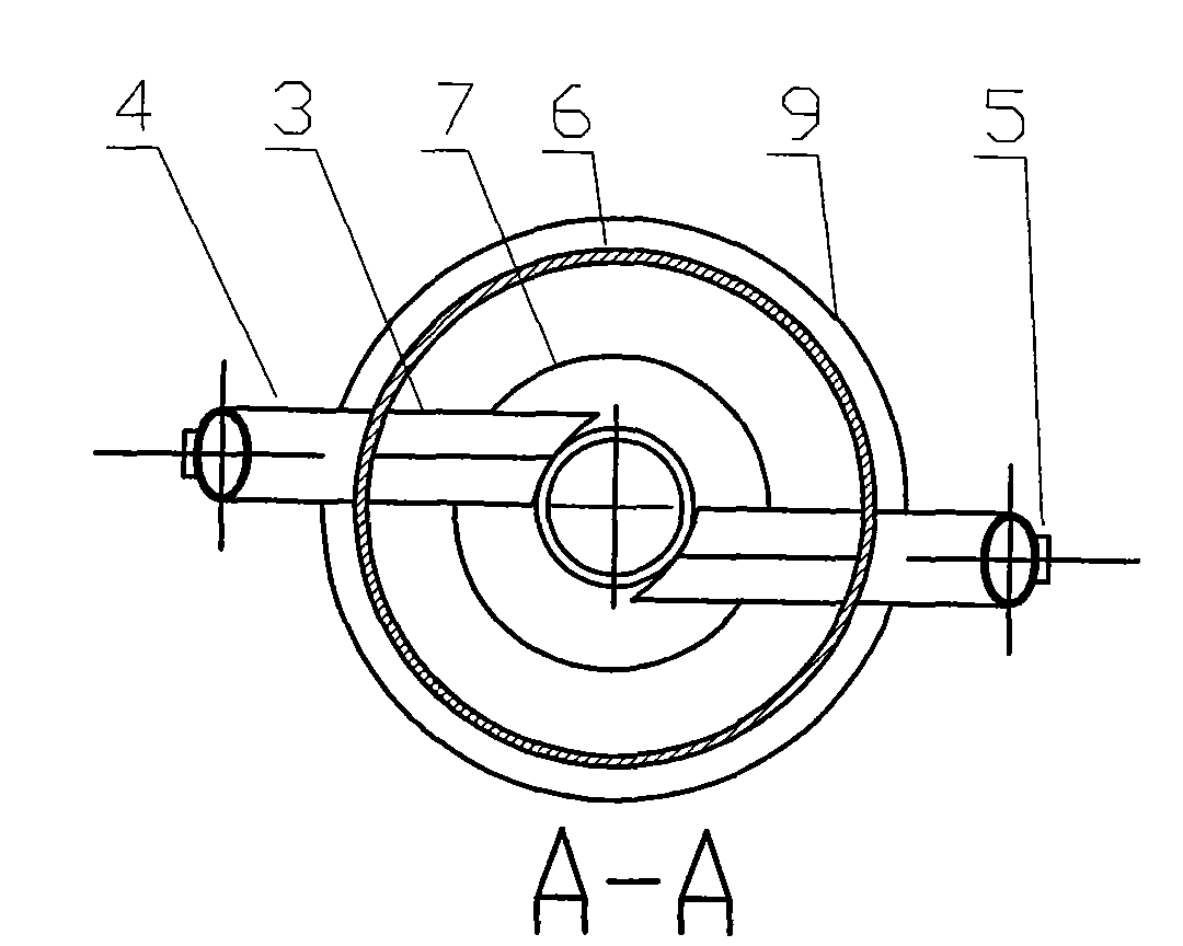
[0027] Embodiment: In the low-quality coal micro-oil ignition burner in the figure, its inlet section (1) is connected with the original pulverized coal pipe, and the air powder separation ring (2) is installed between the inlet section (1) and the light-phase pulverized coal chamber ( 6); the first-level dense-phase pulverized-coal ignition chamber (7) is installed inside the light-phase pulverized-phase coal chamber (6) and is connected with it by a rib plate (8); two oil burners (4) are contained in one The two sides of the dense-phase pulverized coal ignition chamber (7) pass through the light-phase pulverized coal chamber (6); there is a wing-shaped anti-wear block (3) in the powder incoming direction of the oil burner (4), which is connected with the oil burner (4). The burner (4), the primary dense phase pulverized coal ignition chamber (7), and the light phase pulverized coal chamber (6) are welded into one; the flame detection tube (5) is mounted on the oil burner (4) ...


PUM


Abstract

An inferior coal micro-oil ignition combustor comprises a streamlined air powder separation ring, a bidirectional cyclone oil combustor, a wing-shaped anti-friction block, a primary dense-phase coal powder combustion chamber, a secondary dilute-phase coal powder combustion chamber, a V-shaped cavity backflow blunt body, a circumferential cooling bellows and the like, employs a principle of gas-solid two phase flow separation, a principle of oil flame two-way cyclone ignition, backflow high-temperature flue gas of a blunt body, a principle of energy repeated utilization, a principle of coal powder graded ignition and energy gradual enlargement, forms a power field with low air speed, high density, strong eddy flow, strong backflow in the combustor, and creates favorable condition for firing coal powder, so as to effectively solve the problems of firing difficulty and low burn-out ratio of inferior coal. The combustor is capable of igniting inferior coal of 4 to 10 tons by using oil capacity of 150kg/h, which has an oil-saving ratio more than 80%, service life more than 4 years, and is beneficial for popularization in related industries.

Description

technical field [0001] The invention relates to a cold-start and low-load stable combustion device for a boiler in a power plant, especially the design of a low-quality coal-fired boiler. Background technique [0002] At present, there are a large number of power station boilers burning low-quality coal in my country, and their ignition and low-load stable combustion consume a huge amount of oil. A 200MW boiler consumes about 50-70 tons of oil per cold start, a 300MW boiler consumes about 60-80 tons of oil, and a 600MW boiler consumes about 100 tons of oil. According to statistical data, about 4.5 to 5.4 billion yuan is needed for boiler ignition oil every year. [0003] In response to this problem, relevant industry personnel have also done a lot of technical research, but there are still many problems. [0004] For example, Chinese patent ZL200520101974.5 discloses a low-coal and micro-oil cold-state ignition and ultra-low-load stable combustion burner. It has a pulveri...

Claims


Application Information

Patent Timeline
Patent Type & Authority Applications(China)
IPC IPC(8): F23D1/00F23Q9/00
Inventor 闫高程范昌李涛金伟强杨声亮杨晓光霍宇霆
Owner 范昌
Why Eureka
Try Eureka