
Rotationally locked tappet of a valve timing mechanism

A valve driving and anti-rotation technology, which is applied in the direction of valve devices, engine components, machines/engines, etc., can solve the problems of structural space constraints and high requirements for skirt materials that cannot be ruled out

Inactive Publication Date: 2012-10-10
MAHLE INT GMBH
View PDF6 Cites 0 Cited by
  • Summary
  • Abstract
  • Description
  • Claims
  • Application Information

AI Technical Summary

Problems solved by technology

Disadvantageously, due to the length of the clip on the inside of the tappet, the construction space is greatly restricted, in addition, the two legs of the two clips must have a high degree of spring preload in order to ensure the necessary tight fit of the anti-rotation assembly, Thus the use of thin-walled skirts, in particular unacceptably high demands on the skirt material cannot be ruled out

Method used


Image

  • Rotationally locked tappet of a valve timing mechanism
  • Rotationally locked tappet of a valve timing mechanism
  • Rotationally locked tappet of a valve timing mechanism

Examples


Embodiment Construction

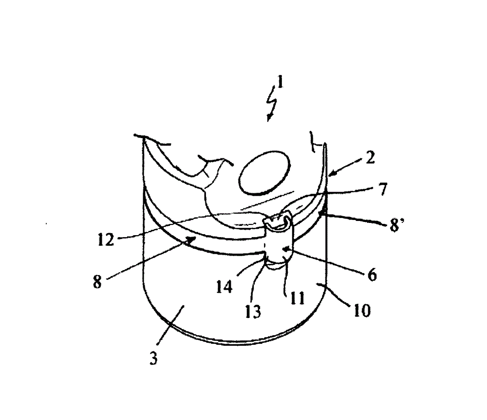
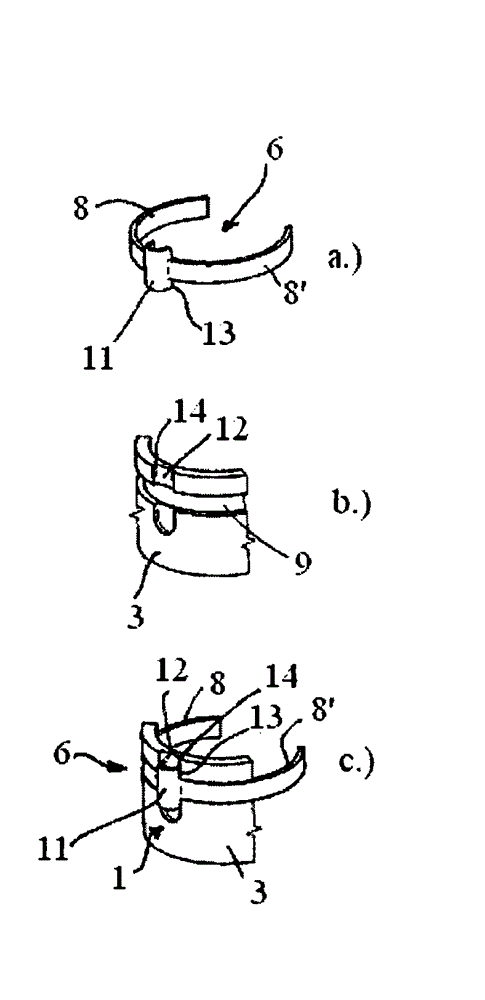
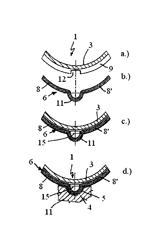
[0028] according to figure 1 , the anti-rotation positioning tappet 1 of the internal combustion engine valve drive has a base plate 2 and an apron 3, wherein the internal combustion engine is not shown. The anti-rotation locking tappet 1 is preferably designed as a piston tappet and is usually placed between a cam and a valve, which are not shown, eg between a control cam and a gas exchange valve. In this arrangement, the tappet 1 carries out an oscillating motion running back and forth in the receiving cylinder of the cylinder head 4, not shown (see image 3 d) A guide groove is provided in the cylinder head 4, wherein the guide groove protrudes radially outwards to engage the anti-rotation assembly 6 of the anti-rotation positioning tappet 1 . The anti-rotation assembly 6 is seated in a recess 7 of the skirt 3 of the tappet 1 .

[0029] according to figure 1 , the anti-rotation assembly 6 has two spring arms 8 , 8 ′ extending in the peripheral direction of the skirt 3 or...


PUM


Abstract

The present invention relates to a rotationally locked tappet (1) of a valve timing mechanism of an internal combustion engine, which tappet is arranged between a cam and a valve and is guided in a receiving bore of a cylinder head (4). Here, a radially protruding anti-rotation safeguard (6) which slides in a guide groove (5) of the cylinder head (4) is arranged in a recess (7, 7') of the skirt (3). It is essential to the invention here that the anti-rotation safeguard (6) has two spring arms (8, 8') which extend in the circumferential direction of the tappet (1), bear at least in regions either against an inner circumferential surface (16) of the skirt (3) or against an outer circumferential surface (10) of the tappet (1) and fix the anti-rotation safeguard (6) on the tappet (1) by a clamping force which acts radially on said tappet (1).

Description

technical field [0001] The invention relates to an anti-rotationally secured tappet, which is preferably used in a valve drive of an internal combustion engine. Background technique [0002] German patent document DE 196 00 852 A1 discloses an anti-rotation positioning tappet of an internal combustion engine valve drive, preferably a bucket tappet mainly composed of a base and a skirt, It is placed between the cam and the valve and is guided in the receiving bore of the cylinder head. An anti-rotation assembly is placed in the recess of the apron, which is guided in a guide groove of the cylinder head. The anti-rotation assembly is designed as an elastic spring element and comprises a back and two clips attached to it, which clips are clamped in two longitudinal slits in the skirt of the tappet. Disadvantageously, due to the length of the clips on the inside of the tappet, the construction space is greatly restricted, in addition, the two legs of the two clips must have a ...

Claims


Application Information

Patent Timeline
Patent Type & Authority Patents(China)
IPC IPC(8): F01L1/14
CPCF01L2107/00F01L1/14F01L1/143F01L2307/00
Inventor 马里奥·普罗科普
Owner MAHLE INT GMBH
Learn More