
Processing method of fuel valve hole of marine diesel engine cylinder cover

A technology of marine diesel engine and processing method, applied in the direction of manufacturing tools, other manufacturing equipment/tools, etc., can solve the problems of long processing time, high processing difficulty, large cutting resistance, etc. The effect of solving positioning difficulties

Inactive Publication Date: 2009-12-23
宁波远达船机配件有限公司
View PDF0 Cites 16 Cited by
  • Summary
  • Abstract
  • Description
  • Claims
  • Application Information

AI Technical Summary

Problems solved by technology

[0004] 1. Since the above-mentioned processing method uses expensive special tools, and the blade is easy to wear and cannot be repaired during processing, the processing cost of the above-mentioned processing method is relatively high
[0005] 2. Due to the large depth of the fuel valve hole, the special tool is greatly affected by the vibrating tool, resulting in poor product quality
[0006] 3. Due to the high cutting resistance of the special tool, the processing speed is relatively slow. It takes 16-24 hours to complete a fuel hole. Therefore, the processing time of the above processing method is relatively long and the processing efficiency is relatively low.
[0007] 4. There are three fuel valve holes in a cylinder head. Due to the spatial angle of the three fuel valve holes, it is very difficult to locate the other fuel valve hole after the previous fuel valve hole is processed, so the processing difficulty of the above method is high.

Method used


Image

  • Processing method of fuel valve hole of marine diesel engine cylinder cover
  • Processing method of fuel valve hole of marine diesel engine cylinder cover
  • Processing method of fuel valve hole of marine diesel engine cylinder cover

Examples


Embodiment Construction

[0030] The present invention will be further described below in conjunction with the accompanying drawings and specific embodiments.

[0031] A kind of processing method of fuel valve hole of cylinder head of marine diesel engine of the present invention adopts common processing machine tool to process, comprises the following steps:

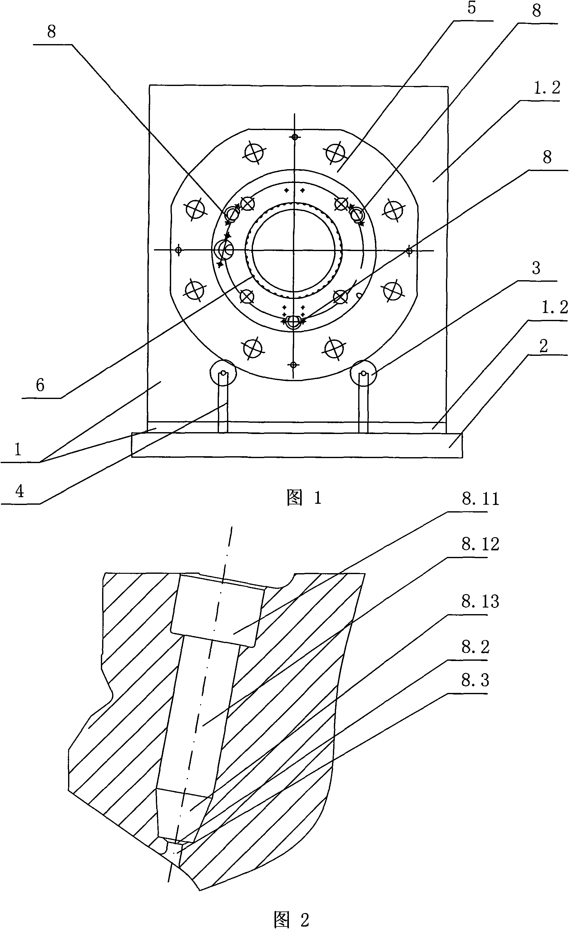
[0032] (1) if figure 1 As shown, the right-angle bending plate is a common auxiliary part in machining; the horizontal plate 1.1 of the right-angle bending plate 1 is fixed on the workbench 2, and the verticality of the right-angle bending plate 1 is corrected, and the two rolling bearings 3 pass through Two columns 4 are fixed on the workbench 2, and the axes of the two rolling bearings 3 are parallel to the axis of the cylinder head 5 of the diesel engine. The cylinder head 5 of the diesel engine is vertically erected on the rolling bearings 3, and the end surface of the cylinder head is perpendicular to the horizontal plane. Position and fa...


PUM


Abstract

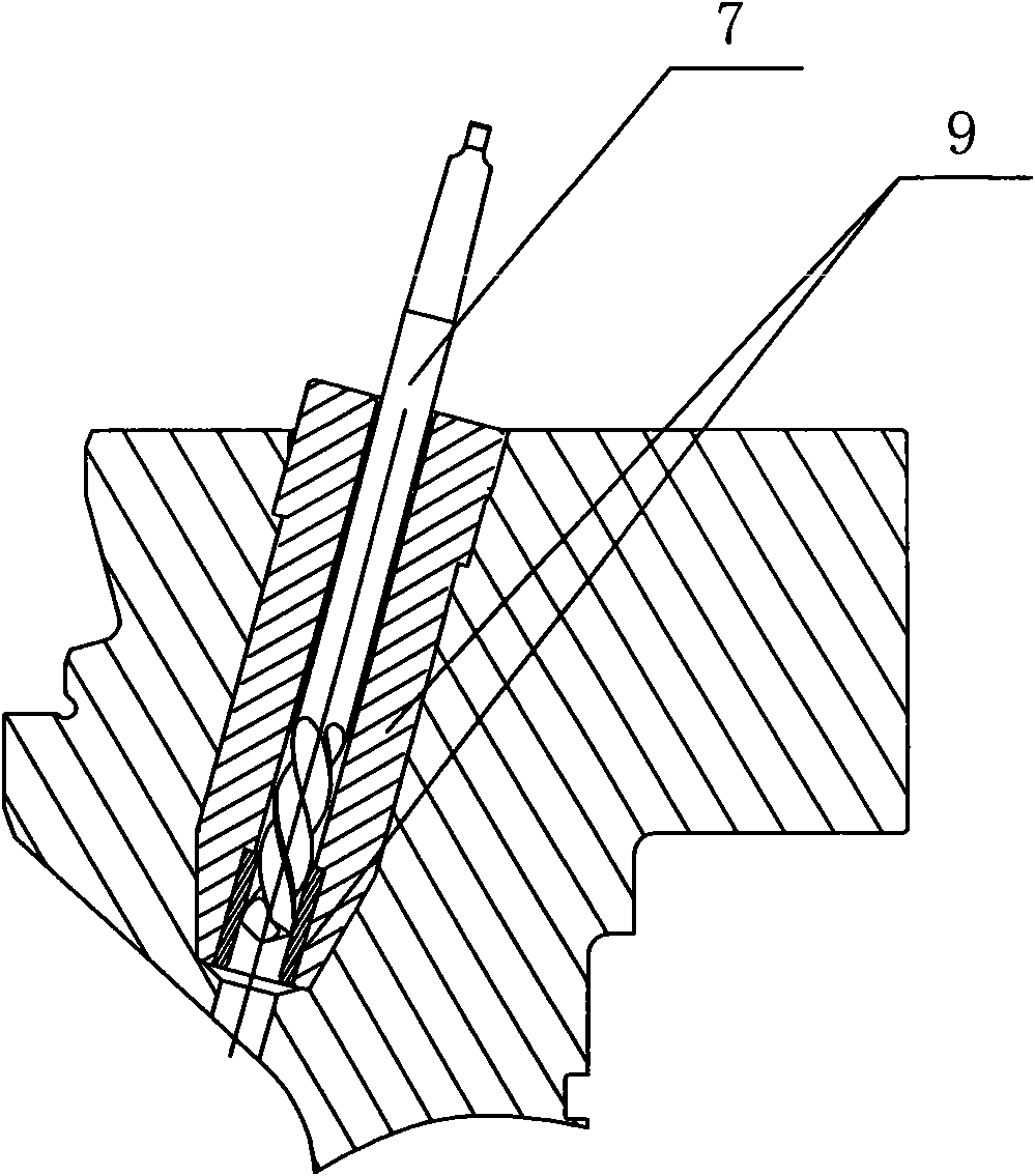
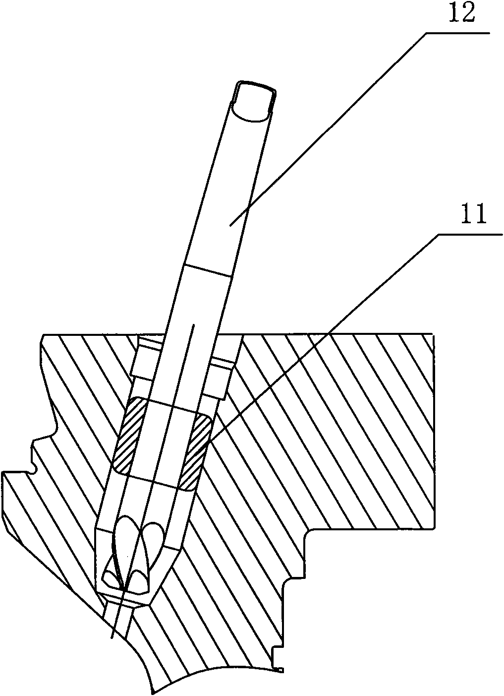
The invention discloses a processing method of a fuel valve hole of a marine diesel engine cylinder cover, comprising the following steps: a right-angle bent plate on a work bench is corrected, a marine diesel engine cylinder cover is fixed on the right-angle bent plate, and then the preset position of a fuel valve hole is drawn; the work bench alpha is vertically rotated, an upward hole is processed by three drills, and then heavy boring and finish boring are carried out; a model drilling body is put into the upward hole, the distance between the model drilling body and the upward hole is h, and a downward hole is processed by a common lengthening drill; the model drilling body is taken out to be put into a bush, parts of middle holes with the distance of d are axially milled by an expanding milling cutter, then a cutter is retreated to take the bush out, and a depth measuring tool is put in to measure residual depth; the depth measuring tool is retreated, then the bush and the expanding milling cutter are put in to mill residual depth so as to mill the middle hole; the cylinder cover on the right-angle bent plate is loosened, and is fixed after rotating; the above steps are repeated to process the residual two fuel valve holes. The above processing method has low processing cost, high quality of processing finished products, short processing time and low processing difficulty.

Description

technical field [0001] The invention relates to a processing method for parts of a marine diesel engine, in particular to a processing method for a fuel valve hole of a cylinder head of a marine diesel engine. Background technique [0002] The fuel valve hole of the marine diesel engine cylinder head is as figure 2 As shown, it includes an upper hole 8.1, a middle hole 8.2 and a lower hole 8.3. The upper hole 8.1 includes three holes with different diameters: a sealing section 8.11, a free section 8.12 and a deep section 8.13. Among them, the upper hole 8.1, the 120° middle hole 8.2, and the lower hole 8.3 of the fuel valve hole of the marine diesel engine cylinder head have a coaxiality tolerance requirement of 0.2mm, which is relatively difficult to process. [0003] In the prior art, the processing of the fuel valve hole of the marine diesel engine cylinder head is mainly processed by a special tool on the workbench at one time. Although the fuel valve hole can also be p...

Claims


Application Information

Patent Timeline
IPC IPC(8): B23P23/02
Inventor 刘海军邵国成
Owner 宁波远达船机配件有限公司
Learn More