
Wire rod rolled product surface processing device

A surface treatment device and steel technology, which is applied in the field of metal surface treatment, can solve the problems of affecting output, efficiency, increasing operating costs, and unsatisfactory results, and achieve the effects of improving efficiency, reducing working time, and smooth and easy transfer

Inactive Publication Date: 2009-12-23
刘传玲
View PDF0 Cites 1 Cited by
  • Summary
  • Abstract
  • Description
  • Claims
  • Application Information

AI Technical Summary

Problems solved by technology

Because the whole coil of steel is long in length and heavy in weight, in the process of processing, one section of steel is processed, the steel is cut off, and another section of steel is processed, which causes time-consuming and labor-intensive problems, which affects output and efficiency, and increases production costs. Operating costs
Moreover, only short-term descaling and rust removal can be performed on the steel, the effect is not ideal, and the efficiency is low.

Method used

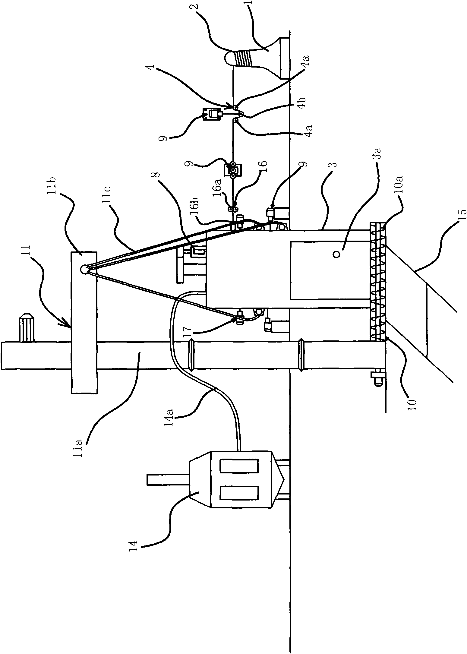
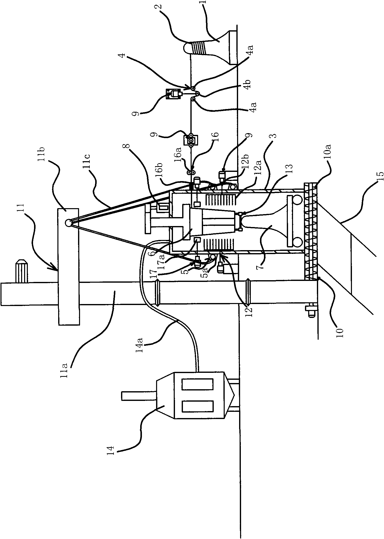
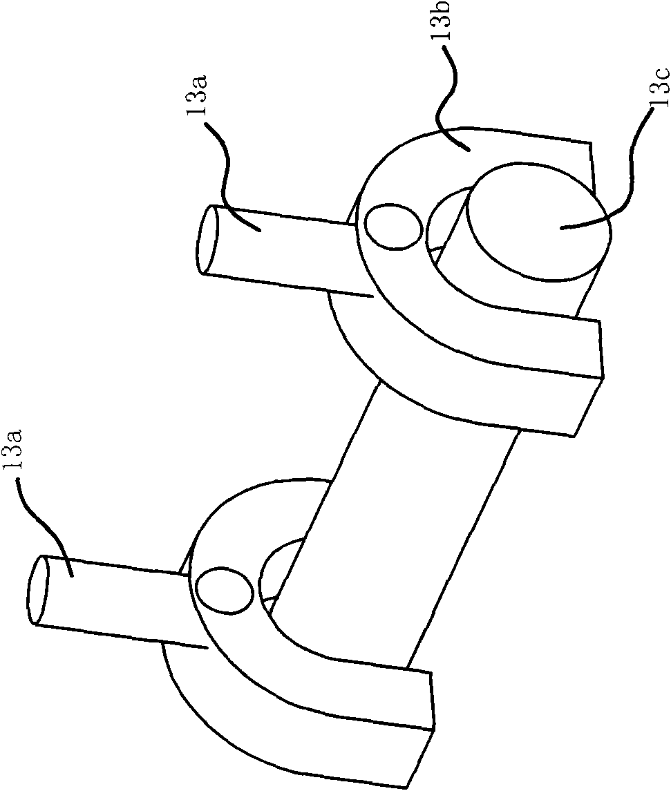

Image

  • Wire rod rolled product surface processing device
  • Wire rod rolled product surface processing device
  • Wire rod rolled product surface processing device

Examples


Embodiment 1

[0036] Such asfigure 1 , figure 2 As shown, the disc round steel surface treatment device includes a discharge drum 1 on which the disc round steel material 2 is placed, a casing 3 and a discharge door 3a located at the bottom of the casing 3 . The feeding drum 1 is placed on a rotating disk with bearings and can rotate. Between the discharge drum 1 and the casing 3, there are two twisting mechanisms 4 capable of bending and deforming the round steel material 2. The twisting mechanism 4 includes two parallel rollers 4a and a pressure roller between the two rollers 4a. 4b, the pressure roller 4b is connected with the power element 9 .

[0037] The entry end of the round steel material 2 enters the inner cavity of the casing 3 through the straightening guide mechanism 16 , and the entry end of the round steel material 2 is wound on the upright drum 6 by the pressing mechanism 17 . Straightening guide mechanism 16 comprises a group of straightening rollers 16a, a guide pipe 16...

Embodiment 2

[0047] The structure and principle of this embodiment are basically the same as that of Embodiment 1, the difference is that, as Figure 4 As shown, the straightening guide mechanism 16 in this embodiment includes a fixed block 18 with a groove, a straightening roller 16a and a guide tube 16b arranged on the casing 3, and a disc circle is pierced in the groove of the fixed block 18. At the entry end of the steel material 2, the straightening roller 16a is located on the side of the fixed block 18 having a groove and is in contact with the groove, and the groove and the guide pipe 16b are in a position facing each other. The entry end of the round steel material 2 is located in the groove of the fixed block 18, rolled and straightened by the straightening roller 16a, and then enters the casing 3 through the guide pipe 16b.


PUM


Abstract

The invention provides a wire rod rolled product surface processing device, belonging to the technical field of metal surface processing. The invention solves the technical problems of small output, low efficiency, increased operation cost, unfavourable effect and the like of the existing wire rod rolled product surface processing device. The wire rod rolled product surface processing device of the invention comprises a material discharging rotary drum on which the wire rod rolled product is arranged, a casing and a material discharging door which is arranged on the lower part of the casing, wherein, the material discharging rotary drum can rotate, the upper part of the inner cavity of the casing is provided with a vertical rotary drum driven to rotate by a motor, and the outer side of the vertical rotary drum is provided with a rust removal mechanism; the inlet end of the wire rod rolled product passes through the casing to enter the inner cavity of the casing, the inlet end of the wire rod rolled product is coiled on the vertical rotary drum by a pressing mechanism, the lower part of the inner cavity of the casing is provided with a rotatable material receiving rotary drum, and the vertical rotary drum is connected with the material receiving rotary drum by a connection structure. The invention has the advantages of high efficiency, favourable descaling effect and rust removal effect and the like.

Description

technical field [0001] The invention belongs to the technical field of metal surface treatment and relates to a surface treatment device for round steel materials. Background technique [0002] During the production and processing of steel, it is often necessary to descale and derust the surface of the steel. The existing descaling and rust removal technologies can be divided into two categories: physical methods and chemical methods. [0003] The chemical method is used to descale and derust the steel. After the completion, the waste water and waste gas generated need to be treated. The facility occupies a large area, the operating cost is high, and it will pollute the environment. Therefore, the use of the chemical method has been restricted. Larger restrictions. The existing physical method mainly adopts sand blasting, shot peening to remove scale and rust, and uses high-speed fans to generate high-speed moving steel grit and steel shot to act on the surface of the proc...

Claims


Application Information

Patent Timeline
IPC IPC(8): B24C3/10B24C9/00
Inventor 刘传玲
Owner 刘传玲
Learn More