Track-type forced landing platform and control process

A rail-based, platform-based technology that can be used in aircraft parts, ground installations, transportation and packaging to solve problems such as aircraft crashes and fatalities

Inactive Publication Date: 2009-12-23
晏明春
View PDF0 Cites 7 Cited by
  • Summary
  • Abstract
  • Description
  • Claims
  • Application Information

AI Technical Summary

Problems solved by technology

After the landing gear of the fighter plane loses its function, it often causes major accidents such as plane crash and human death when it lands

Method used


Image

  • Track-type forced landing platform and control process
  • Track-type forced landing platform and control process
  • Track-type forced landing platform and control process

Examples


Embodiment Construction

[0015] The present invention is explained in more detail below with reference to the accompanying drawings and typical implementation applications.

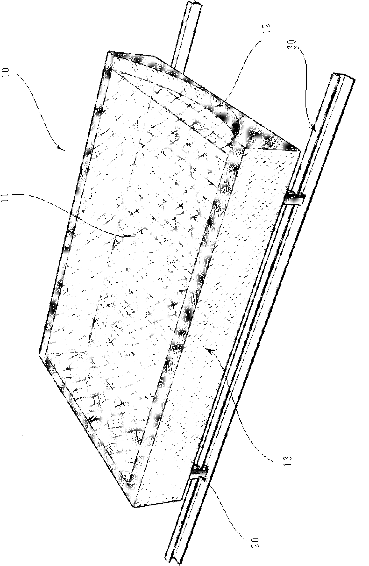
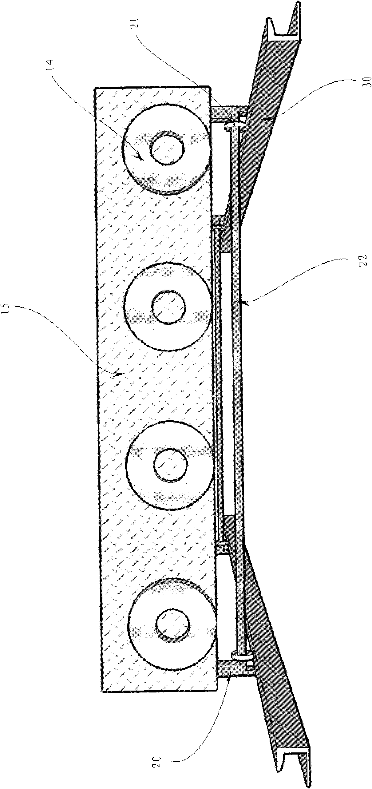
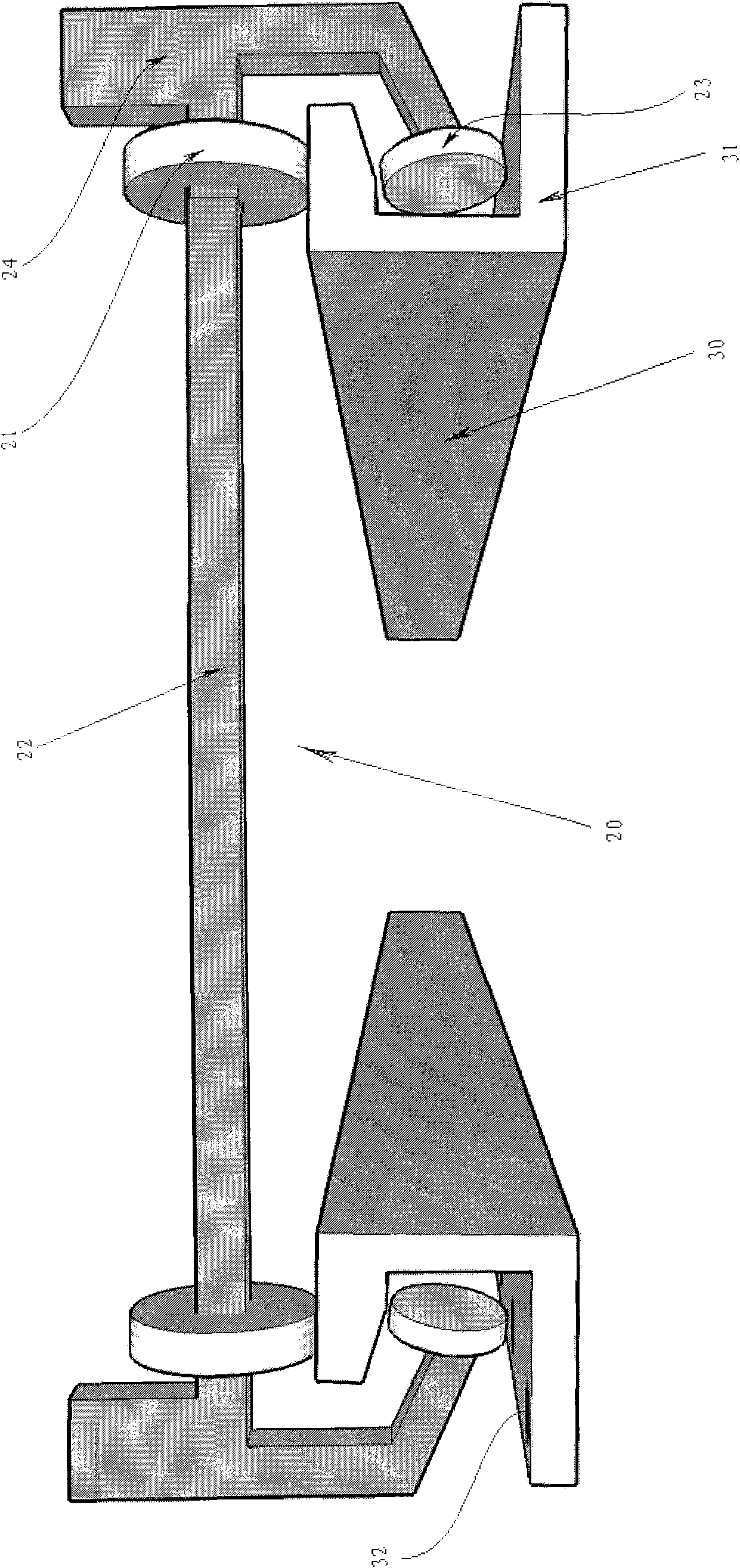
[0016] See figure 1 , the technical problem to be solved in the present invention is to provide an orbital forced landing platform and a control process, including the following components: an aircraft implantation bed 10, on which the aircraft implantation bed 10 is equipped with a buffer net pad 11, a hanging net protection groove 13, an aircraft The implantation chassis, the nose overflow port 12 and at least four external power equipment connection seats 14, when the aircraft is forced to land, the aircraft implantation 10 is used as the receiving object, because the implantation 10 has the above-mentioned cushioning mesh pad 11. It can reduce the destructive force caused by the impact. The hanging net protection groove 13 on the implantation bed 10 can protect the aircraft implantation bed 10 caused by the deviation of aircr...


PUM


Abstract

The invention relates to a track-type forced landing platform, which has a structure comprising an airplane landing bed, a forced landing platform rack and a straight track. With a straight track mode, the track-type forced landing platform can meet the requirements for the straight high-speed sliding motion of an airplane forced to land, reduces the impulse force generated when the airplane force to land lands by using the cushioning action of the airplane landing bed and improves the safe forced landing rate of the airplane.

Description

technical field [0001] The invention relates to a rapid track platform for backup when the aircraft fails to land when the aircraft lands or the airport cannot provide a landing taxiway for the aircraft due to an emergency, and particularly relates to the emergency forced landing technology of the military airport aircraft. Background technique [0002] At present, when an aircraft is forced to land, most of them use runway to set up a block or spread lubricant on the ground. Various inventions have been proposed for this problem, such as the patent "Aircraft Landing Gear Failure Forced Landing Trailer" Patent Application No. 200510019929X, which uses a car to drag mode to make an emergency landing of the aircraft to achieve the purpose of safe landing, but the invention is based on the perfect runway of the airport. Once the airport is destroyed and the runway cannot be provided, the patented technology exists if the runway may be missing. When the road is uneven, or there ...

Claims


Application Information

Patent Timeline
Patent Type & Authority Applications(China)
IPC IPC(8): B64F1/00
Inventor 晏明春
Owner 晏明春
Why Eureka
Try Eureka