

Optical refractometry measuring method and device
A measurement method and a technology of a measurement device, which are applied in the direction of a measurement device, an optical instrument test, a reflectometer for detecting backscattered light in the frequency domain, etc., can solve the problems of inability to perform measurement, broadening of the spectrum width of beat frequency signals, and resolution Deterioration and other issues
- Summary
- Abstract
- Description
- Claims
- Application Information
AI Technical Summary
Problems solved by technology
Method used
Image

Examples
no. 1 approach
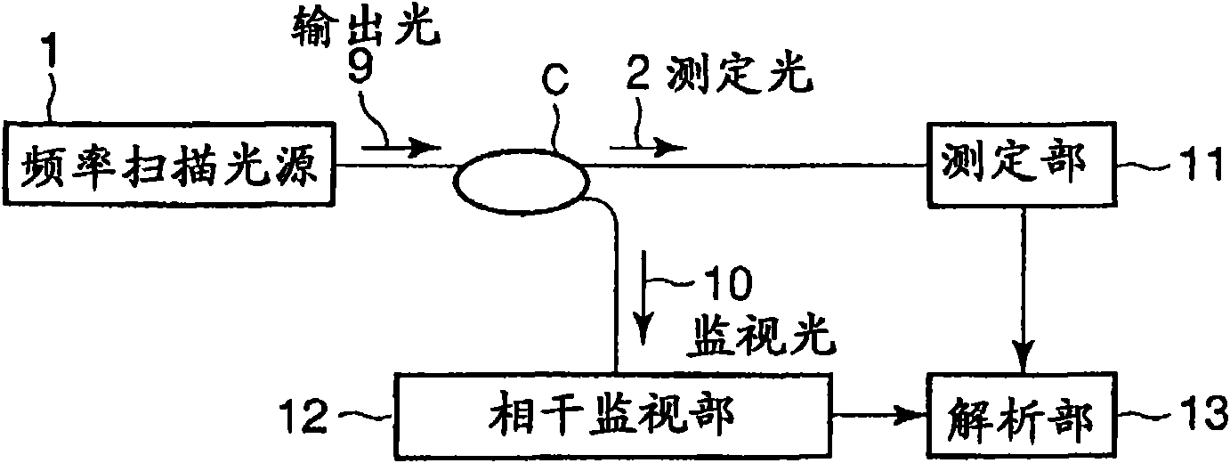
[0076] image 3 It is a functional block diagram showing an embodiment of the light reflection measurement device of the present invention. This optical reflectance measurement device performs OFDR measurement of the distribution of reflectance with respect to the propagation direction in a circuit to be measured. exist image 3 Among them, the output light 9 from the frequency-sweeping light source 1 is branched by the optical directional coupler C, one of which enters the measurement unit 11 as the measurement light 2 , and the other enters the coherence monitoring unit 12 as the monitor light 10 . The results measured by the measurement unit 11 and the results monitored by the coherence monitoring unit 12 are input to the analysis unit 13, and the backscattered light intensity distribution in the measured circuit (inside the measurement unit 11) is obtained through arithmetic processing.
[0077] The measurement unit 11 detects the interference beat signal of the output l...
no. 2 approach
[0118] In the first embodiment, it is possible to optimally correct the c The beat frequency signal generated by the backscattered signal light at the point / 2. However, as the assay point changes from NL c / 2 distance, the correction accuracy deteriorates. In the second embodiment, a processing method capable of avoiding deterioration of correction accuracy will be described. In this embodiment, the basic structure of the device is the same as Figure 4 Similarly, the processing by the data processing unit 18a is different.
[0119] As described in the first embodiment, the correction process using equation (11) is at distance NL c / 2 is best. After correction, the beat frequency F corresponding to this distance N becomes a constant and is represented by the following formula (14).
[0120] f N = f N (t) β(t) (14)
[0121] In formula (14), f N (t) is the time differential X' of formula (11) N (t)(=dX N (t) / dt), represents the instantaneous beat frequency. β(t) i...
no. 3 approach
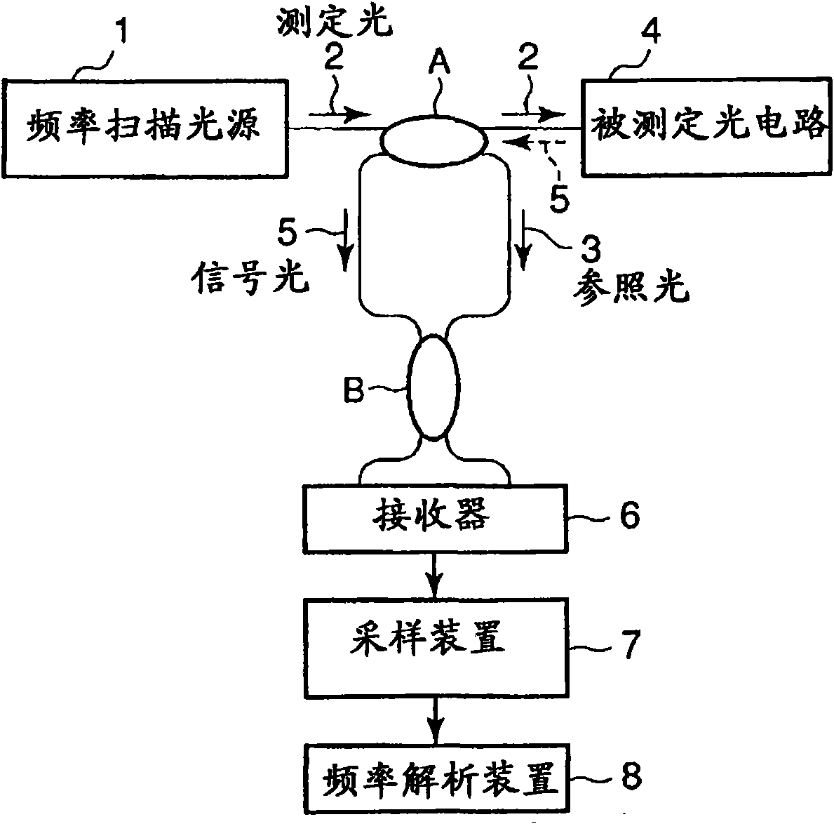
[0162] Figure 13 It is a figure which shows an example of the basic structure of the optical reflectance measurement apparatus by OFDR. exist Figure 13 In the above, the output light from the frequency-sweeping light source 1 is branched through the optical directional coupler A, one is used as the reference light 3 , and the other is injected into the optical circuit 4 to be measured. The signal light 5 backscattered inside the optical circuit 4 to be measured is taken out by the optical directional coupler A, combined with the reference light 3 by the optical directional coupler B, and then detected by the receiver 6 . At this time, the interference beat signal generated due to the interference of the two light waves is sampled by the sampling device 7, and the measured data is analyzed by the frequency analysis device 8, thereby measuring the signal from each position in the optical circuit 4 to be measured. The backscattered light intensity distribution at .
[0163] ...
PUM
 Abstract
Description
Claims
Application Information