Anti-shake device of mobile robotic vision system and anti-shake compensation control method therefor
A mobile robot and vision system technology, applied in the direction of manipulators, manufacturing tools, etc., can solve the problem of active compensation and control of mobile robot jitter, the vision device jitter imaging is not clear, and it is difficult to apply to the complex and irregular jitter of mobile robots environmental issues
- Summary
- Abstract
- Description
- Claims
- Application Information
AI Technical Summary
Problems solved by technology
Method used
Image
Examples
specific Embodiment approach 1
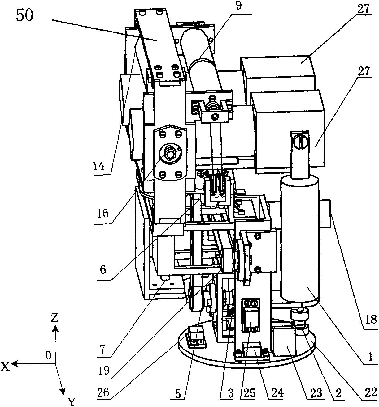
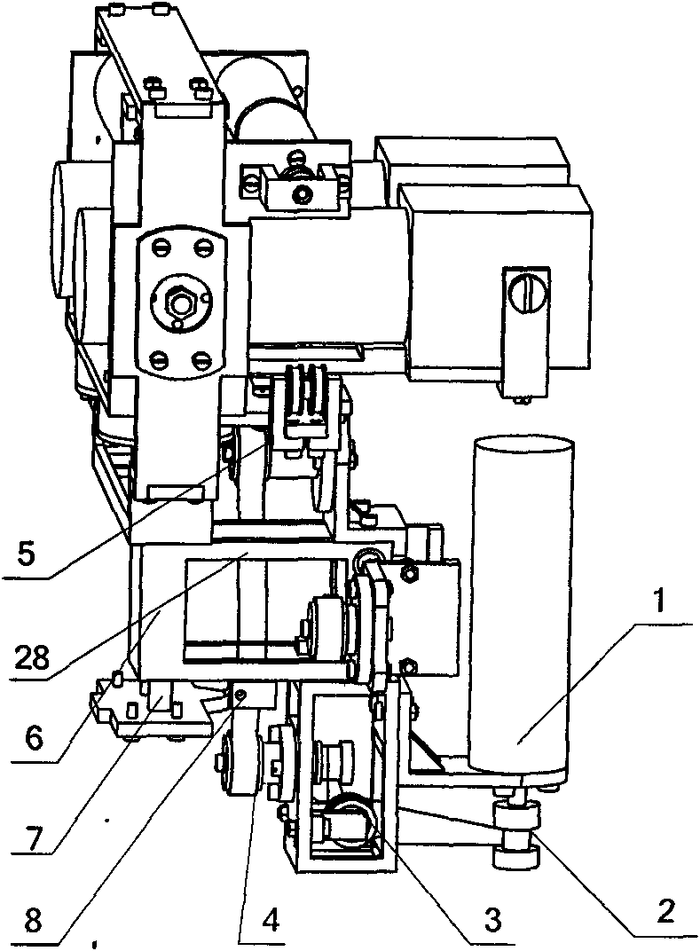
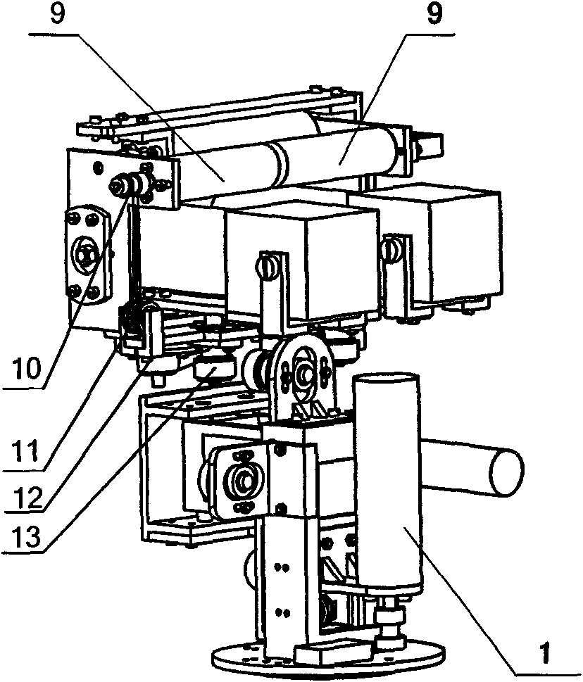
[0026] Specific implementation mode one, the following combination Figure 1a-1f , figure 2 Description of this embodiment: the mobile robot vision system anti-shake device described in this embodiment is composed of three parts: an anti-shake mechanism, a sensor system and an anti-shake control system; , a yaw unit and a base 22, the up and down movement unit, the left and right movement unit, the pitch unit and the yaw unit are all arranged on the base 22; the sensor system includes an inclination sensor 26, a first vibration sensor 24 and a second vibration sensor Sensor 25, tilt sensor 26, the first vibration sensor 24 and the second vibration sensor 25 are all installed on the base 22, and the tilt sensor 26 measures the rotation angle of the base 22 relative to the X-axis direction and the Y-axis direction respectively; the first vibration sensor 24 , The second vibration sensor 25 measures the movement of the base 22 along the Z-axis direction and the Y-axis direction...
specific Embodiment approach 2
[0035] Specific embodiment two, combine image 3 , Figure 4 , Figure 5 , Image 6 Describe this embodiment, the anti-shake compensation control method of the mobile robot vision system anti-shake device described in this embodiment is:
[0036] Step 1, the vibration parameter h measured by the first vibration sensor 24, the second vibration sensor 25 and the inclination sensor 26 1 、h 2 , and the corresponding difference to determine the velocity and acceleration of the measured jitter change;
[0037] Step 2. According to the situation measured by the sensor system within the sampling time T, it is judged whether there is jitter in the vision system of the mobile robot; if jitter needs to be compensated, perform step 3; otherwise, no compensation is required;
[0038] Step 3. Calculate the compensation amount: establish the D-H coordinate system of each kinematic joint to describe the translation between adjacent rods a 1 、a 2 and rotate θ 3 , θ 4 , θ 5 The rela...
specific Embodiment approach 3
[0050] Specific implementation mode three, the following combination Figure 7 To illustrate this embodiment, the vision system anti-shake device of the present invention can be applied to a humanoid robot 30 . The vision system anti-shake device can be used as the head of the humanoid robot, and is fixedly connected with the interface on the neck 31 of the humanoid robot 30 through the device base 22 . The anti-shake control system 23 in the anti-shake device of the vision system is used as the bottom control system of the anti-shake control, and is connected with the upper control machine in the chest of the humanoid robot 30 through a control line and a data line.
PUM
 Abstract
Description
Claims
Application Information
 - R&D
- Intellectual Property
- Life Sciences
- Materials
- Tech Scout
- Unparalleled Data Quality
- Higher Quality Content
- 60% Fewer Hallucinations
Browse by: Latest US Patents, China's latest patents, Technical Efficacy Thesaurus, Application Domain, Technology Topic, Popular Technical Reports.
© 2025 PatSnap. All rights reserved.Legal|Privacy policy|Modern Slavery Act Transparency Statement|Sitemap|About US| Contact US: help@patsnap.com


