Automatic rope distributing and discharging device of winch

An automatic rowing and winch technology, applied in the direction of hoisting device, clockwork mechanism, etc., can solve the problems of limited winch space, slow descending speed, loose and messy rowing rope, etc., to achieve strong practicability and applicability, and convenient disassembly The effect of replacing and avoiding potential accidents

Inactive Publication Date: 2009-12-30
泰安巨菱钻探装备有限责任公司
View PDF0 Cites 27 Cited by
  • Summary
  • Abstract
  • Description
  • Claims
  • Application Information

AI Technical Summary

Problems solved by technology

[0002] The winches include pneumatic winches, hydraulic winches, and electric winches. As power equipment for traction and lifting, winches are widely used in oil fields, geological drilling, mining and other places. There has never been an effective rope discharge mechanism, without exception. There is a fatal shortcoming that the ropes are easy to loosen and messy, especially for oilfield drilling rigs and similar oilfield drilling rigs. Most of the winches are basically vertically upward, and the height of the pulley to the winch is generally 30-50m. The disordered rope is more prominent under the condition of no load. If the speed of the reel is fast, and the steel wire rope on the other side of the sky pulley is slow due to no load, the wire rope on the reel will be fluffy and scattered. , and when lifting heavy objects, it may occur that the heavy objects stop for a certain distance at a certain moment. Because of this shortcoming, almost every oil field pays a high price of life every year
Over the years, many people at home and abroad have been exploring in this area, but have not found a better solution, because there are many devices on the drilling rig platform, and the space for placing the winch is limited, which requires that the mechanism should not be too large. Complicated and huge, but also able to effectively solve existing problems

Method used


Image

  • Automatic rope distributing and discharging device of winch
  • Automatic rope distributing and discharging device of winch
  • Automatic rope distributing and discharging device of winch

Examples


Embodiment Construction

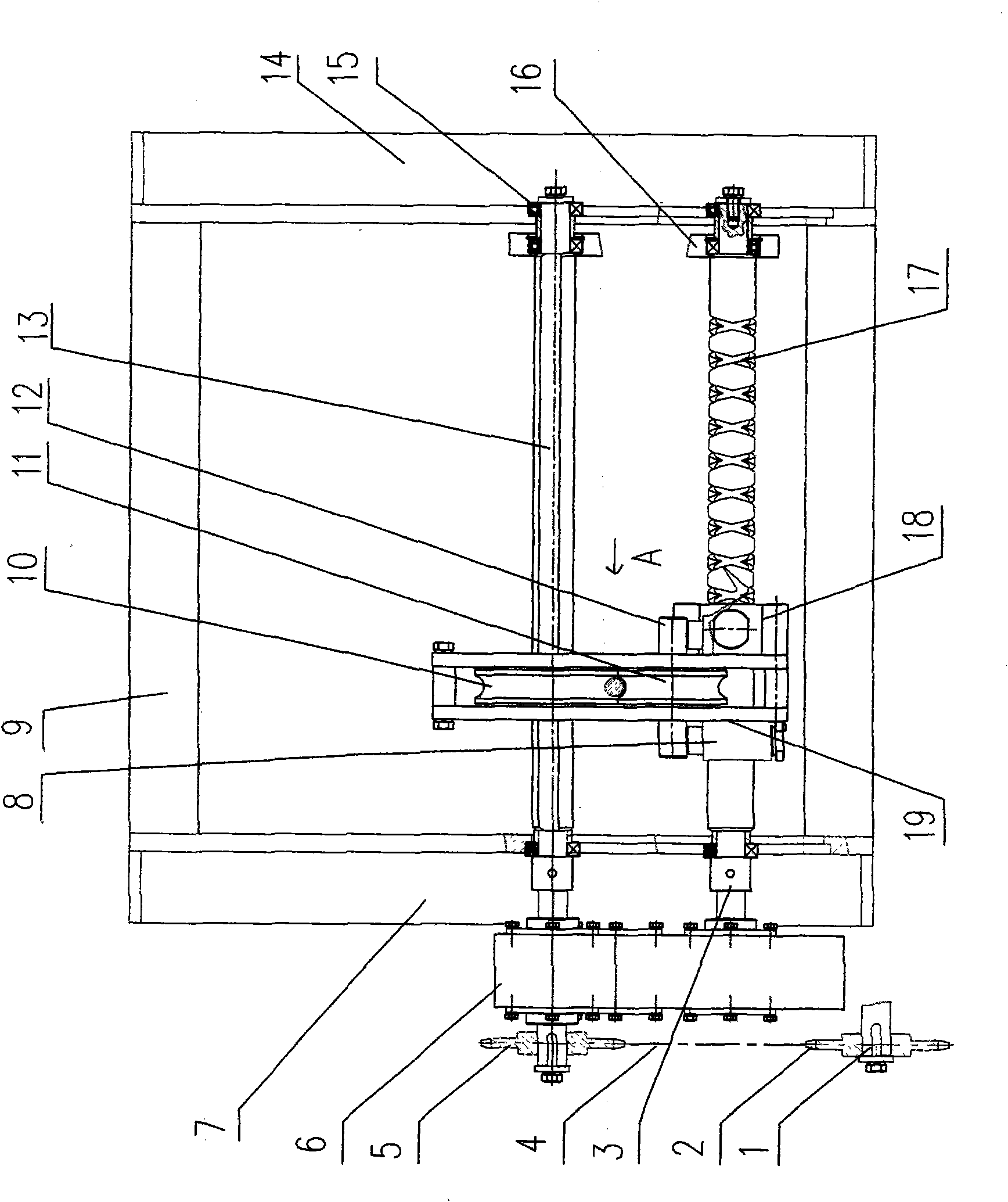
[0013] From figure 1 As can be seen from the structural schematic view of the automatic rowing and rope-out device of the winch of the present invention, the present invention includes a gear box 6 and a rope-out mechanism, and the rope-out mechanism includes a two-way lead screw 17, a ratchet shaft 13, a rope pulley 10, a pressure pulley Sheave 11 and slide block 18, two-way lead screw 17 and ratchet shaft 13 are installed in parallel on left support plate 7 and right support plate 14, and speed distribution box 6 is arranged on the transmission shaft of two-way lead screw 17 and ratchet shaft 13 one ends superior. The present invention is placed on the top or the side of the winch in use, and is fixed on the base of the winch by four columns linking to each other with the left and right support plates 7,14.

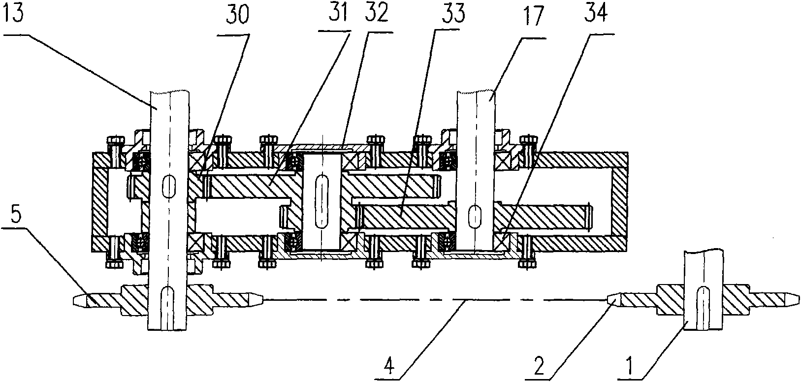
[0014] From image 3 It can be seen from the schematic diagram of the structure of the gearbox part that the power is obtained from the appropriate position of the tr...


PUM


Abstract

The invention discloses an automatic rope distributing and discharging device of a winch, which comprises a speed-setting box and a rope discharging mechanism, wherein the rope discharging mechanism comprises a bidirectional screw, a ratchet shaft, a rope driving wheel, a rope pressing wheel and a slide block, the rope driving wheel is arranged on the ratchet shaft, the rope pressing wheel is correspondingly arranged outside the rope driving wheel, two sides of the rope pressing wheel are provided with compacting devices, the slide block is arranged on the bidirectional screw, and a ratchet pin is arranged between the rope driving wheel and the ratchet shaft. The invention has novel design, reasonable structure and high safety property, can not only lead a rope to be automatically sequentially distributed on a winding drum, can lead the rope to be forcedly driven out when placing the rope, and can be applied to various winches used under different conditions and environments.

Description

technical field [0001] The invention belongs to the technical field of traction and hoisting equipment, and in particular relates to an automatic rope discharge and discharge device applied to a winch. Background technique [0002] The winches include pneumatic winches, hydraulic winches, and electric winches. As power equipment for traction and lifting, winches are widely used in oil fields, geological drilling, mining and other places. There has never been an effective rope discharge mechanism, without exception. There is a fatal shortcoming that the ropes are easy to loosen and messy, especially for oilfield drilling rigs and similar oilfield drilling rigs. Most of the winches are basically vertically upward, and the height of the pulley to the winch is generally 30-50m. The disordered rope is more prominent under the condition of no load. If the speed of the reel is fast, and the steel wire rope on the other side of the sky pulley is slow due to no load, the wire rope on...

Claims


Application Information

Patent Timeline
Patent Type & Authority Applications(China)
IPC IPC(8): B66D1/395
Inventor 谢学山王昌利李伟民段全虎杨延强张灿峰
Owner 泰安巨菱钻探装备有限责任公司
Why Eureka
Try Eureka