Pretensioning prestressed concrete pile, stretch-draw anchoring piece thereof and method for manufacturing stretch-draw anchoring piece

A technology for concrete piles and a manufacturing method, which is applied in the directions of manufacturing tools, sheet pile walls, reinforcing molding, etc., can solve the problems of low production efficiency, waste of raw materials, and labor intensity of easily corroded workers, so as to improve quality, save materials, and reduce labor. The effect of labor intensity

Inactive Publication Date: 2009-12-30
盐城市同力新型建材有限公司
View PDF0 Cites 17 Cited by
  • Summary
  • Abstract
  • Description
  • Claims
  • Application Information

AI Technical Summary

Problems solved by technology

[0005] The purpose of the present invention is to design a method that can not only ensure the overall tension of the main reinforcement, but also solve the problems of waste of raw materials, easy corrosion, high labor intensity and low production efficiency of the existing pre-tensioned prestresse

Method used


Image

  • Pretensioning prestressed concrete pile, stretch-draw anchoring piece thereof and method for manufacturing stretch-draw anchoring piece
  • Pretensioning prestressed concrete pile, stretch-draw anchoring piece thereof and method for manufacturing stretch-draw anchoring piece
  • Pretensioning prestressed concrete pile, stretch-draw anchoring piece thereof and method for manufacturing stretch-draw anchoring piece

Examples


Embodiment 1

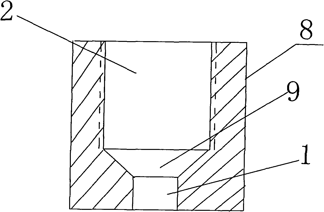
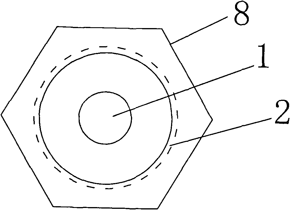
[0038] Such as figure 1 , 2 shown.

[0039] A tension anchor for pre-tensioned prestressed concrete piles, comprising a stainless steel body 8, the body 8 is provided with interpenetrating screw holes 2, countersunk holes 1, and connecting screw holes 2 and countersunk holes 1 Transition hole 9, the diameter of the sinking reinforcement hole 1 matches the diameter of the prestressed main reinforcement, the aperture of the screw hole 2 is larger than the aperture of the sinking reinforcement hole 1, and the described sinking reinforcement hole 1 is a cylindrical hole or a polygonal column hole. In order to prevent the main body 8 from losing its effect under the force rotation in concrete during specific implementation, so the end face profile of the main body 8 can be designed into a polygon (such as triangle, quadrangle, pentagon, hexagon, heptagon, octagon, nine sides) shape,...etc.), it can also be designed as a columnar anti-rotation structure consisting of at least one ...

Embodiment 2

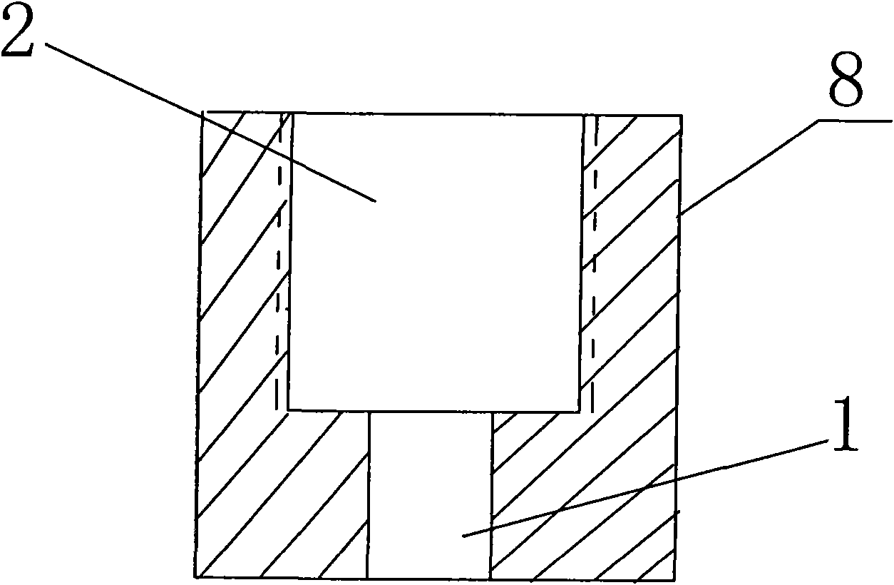
[0041] Such as image 3 shown.

[0042] The difference between this embodiment and Embodiment 1 is that the screw hole 2 directly communicates with the columnar countersunk hole 1 where the main steel bar is worn, and the step surface at the bottom of the screw hole is offset against the heading of the main steel bar so as to prevent the main steel bar from coming out of the body 8. fall off.

Embodiment 3

[0044] Such as Figure 4 shown.

[0045] The difference between this embodiment and Embodiment 1 is that the screw hole 2 directly connects with the tapered countersunk hole of the main steel bar, and the upset head of the main steel bar directly offsets the conical surface of the countersunk hole of the cone. The size of the head is larger than the size of the small end of the tapered countersunk hole, so it can also play a role in preventing the body from falling off the main steel bar.


PUM


Abstract

The invention discloses a stretch-draw anchoring piece for a pretensioning prestressed concrete pile, a pile body structure thereof and a method for manufacturing the stretch-draw anchoring piece. The stretch-draw anchoring piece is the key of the invention. The stretch-draw anchoring piece comprises a body (8), wherein the body (8) is provided with screw pores (2) mutually running through, a tendon settling pore (1) and a transitional pore (9) for connecting the screw pores (2) and the tendon settling pore (1); the pore diameter of the tendon settling pore (1) is matched with the diameter of a prestressed main tendon; the pore diameter of each screw pore (2) is larger than that of the tendon settling pore (1); and the tendon settling pore (1) is a cylindrical pore or a polygon prism pore. The stretch-draw anchoring piece has the advantages of simple structure and convenient manufacture, and can greatly reduce the manufacturing cost and the cost of raw materials.

Description

technical field [0001] The invention relates to a prefabricated concrete pile, in particular to a cost-saving concrete pile without an end plate, in particular to a pre-tensioned prestressed concrete pile and its tension anchor and a manufacturing method. Background technique [0002] As we all know, pretensioned prestressed concrete piles are currently the most widely used pile foundation materials, including pretensioned prestressed concrete pipe piles and pretensioned prestressed concrete hollow square piles. At present, the production method of on-site casting has been changed in the past, and the quality-guaranteed factory workshop assembly line production process is mostly used. [0003] Concrete piles are slender components with a large length-to-diameter ratio, and ring cracks are prone to occur during production, transportation and construction. In order to make up for this defect and achieve the purpose of saving steel, factory production often adopts prestressed p...

Claims


Application Information

Patent Timeline
IPC IPC(8): E02D5/58E02D5/30B28B21/60B28B21/90
Inventor 唐书斌龙章松宋峰
Owner 盐城市同力新型建材有限公司
Why Eureka
Try Eureka