Method and device for diagnosing the ventilation in crankcase of internal combustion engine

A technology for crankcase ventilation and internal combustion engine, which is applied in the functional field of diagnosing crankcase ventilation, and can solve problems such as leakage, pressure increase, leakage of squeezed oil dipstick, etc.

Inactive Publication Date: 2009-12-30
ROBERT BOSCH GMBH
View PDF0 Cites 26 Cited by
  • Summary
  • Abstract
  • Description
  • Claims
  • Application Information

AI Technical Summary

Problems solved by technology

For example, a blockage of the ventilation duct between the oil separator and the air system can result in an increase in pressure in the crankcase, which can lead to leaks
Especially the pressure increase in the crankcase due to extrusion of the dipstick e.g. causing leaks

Method used


Image

  • Method and device for diagnosing the ventilation in crankcase of internal combustion engine
  • Method and device for diagnosing the ventilation in crankcase of internal combustion engine

Examples


Embodiment Construction

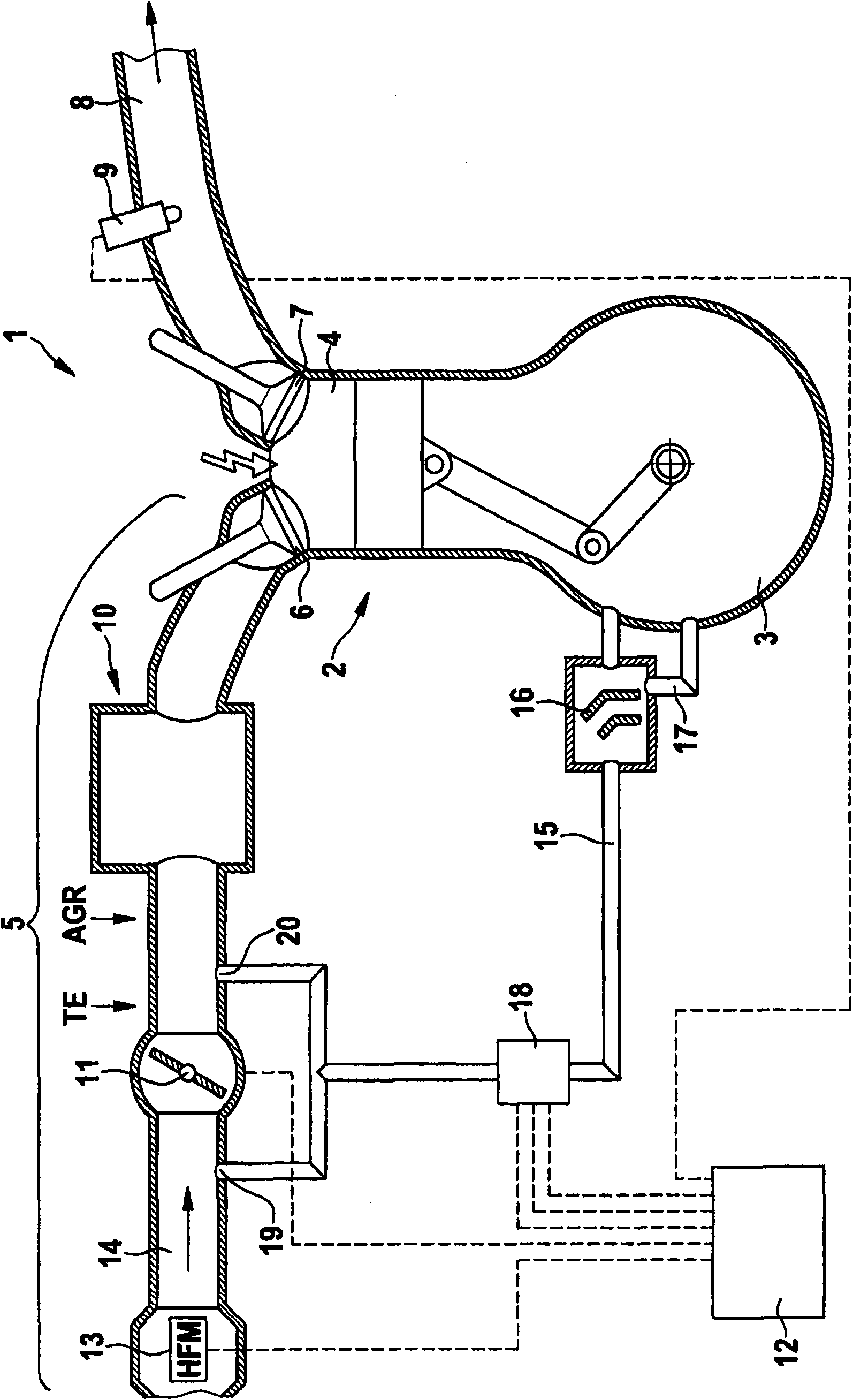
[0034] figure 1 The schematic diagram shows the engine system 1 . An internal combustion engine 2 with cylinders 4 and a crankcase 3 is shown in the engine system. For the sake of clarity, internal combustion engine 2 is shown with only one cylinder 4 . Air cylinders 4 are supplied with air via an air system 5 . Air enters the corresponding cylinder 4 via the intake valve 6 . Combustion exhaust gases can be discharged from the cylinders 4 into an exhaust manifold 8 via an exhaust valve 7 . An excess air ratio probe 9 is provided in the exhaust manifold 8 to detect the mixture composition of the burned air-fuel mixture and provide data on the excess air ratio value. Fuel is supplied to the cylinders 4 either directly or indirectly via the air system 5 .

[0035] The air system 5 includes an intake pipe 10 and a throttle valve 11 for adjusting the intake air volume of the cylinder 4 . The intake pipe 10 is provided between the throttle valve 11 and the intake valve 6 . Fu...


PUM


Abstract

The invention relates to a method and a device for diagnosing the ventilation in a crankcase of an internal combustion engine. The invention relates to a method for detecting the function of a crankcase ventilation system of an engine system with the internal combustion engine, wherein, the method comprises the following steps of: blocking off a ventilation pipeline between the crankcase of the internal combustion engine and an air system during the duration of detection; determining the variation of operating parameters of the internal combustion engine during the duration of detection; and determining the failure of the crankcase ventilation system in virtue of the determined variation of the operating parameters.

Description

technical field [0001] The present invention relates to crankcase ventilation of internal combustion engines, and more particularly to a method and device which can be used to diagnose the function of the crankcase ventilation. Background technique [0002] When the internal combustion engine is running without ventilation, a higher pressure than the atmospheric pressure can build up in the crankcase. This pressure is mainly caused by the escape of combustion gases from the combustion chamber (blow-by) and the formation of oil mist. In order to avoid such high pressure in the crankcase, the crankcase and the air system are usually connected by means of one or more ventilation ducts through the oil separator, so that this mixture is delivered to the combustion in the cylinders through the intake system, while the Will not reach atmospheric environment. [0003] Usually the ventilation line opens both into the region of the air system upstream of the throttle valve and into ...

Claims


Application Information

Patent Timeline
Patent Type & Authority Applications(China)
IPC IPC(8): F01M13/00F01M11/10
CPCF02D41/221F01M13/022F01M2013/0427F01M13/023F02D41/1454Y02T10/40F02D41/003F01M2013/0022F01M2013/0005F01M13/00
Inventor J·瓦尔
Owner ROBERT BOSCH GMBH
Why Eureka
Try Eureka