Construction machinery

A technology for construction machinery and engines, applied in the direction of exhaust devices, etc., can solve the problems of poor assembly workability, inability to install, and difficult to install shields, and achieve the effect of improving assembly workability.

Active Publication Date: 2009-12-30
HITACHI CONSTR MASCH CO LTD
View PDF2 Cites 8 Cited by
  • Summary
  • Abstract
  • Description
  • Claims
  • Application Information

AI Technical Summary

Problems solved by technology

Therefore, it is difficult to install the shield in a narrow place between the exhaust gas treatment device and the hydraulic pump, and labor and time are required for installation.
In ad

Method used


Image

  • Construction machinery
  • Construction machinery
  • Construction machinery

Examples


Example Embodiment

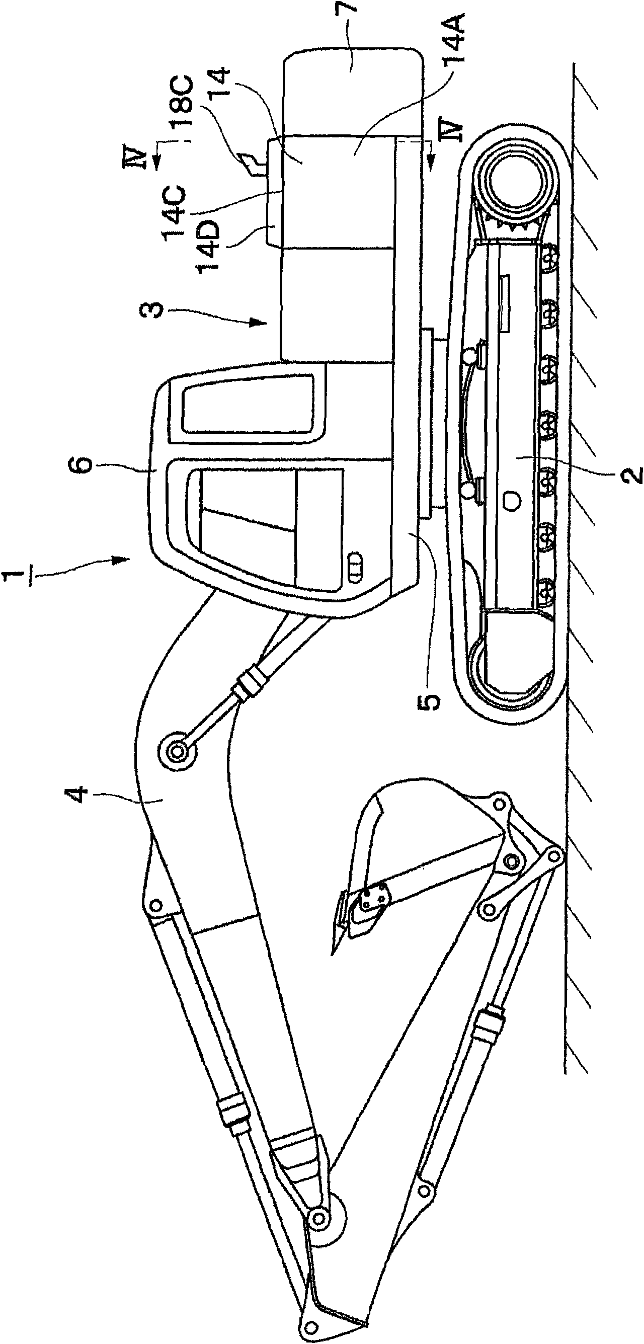
[0042] Hereinafter, as a construction machine of an embodiment of the present invention, a crawler hydraulic excavator is taken as an example, according to Figure 1 to Figure 12 It will be explained in detail.

[0043] in figure 1 In the figure, mark 1 is a crawler hydraulic excavator as a construction machine. The hydraulic excavator 1 roughly includes: a lower traveling body 2 capable of being self-propelled; rotatably mounted on the lower traveling body 2 and together with the lower traveling body 2 The upper revolving body 3 constituting the vehicle body; and a working device 4 that is installed on the front side of the upper revolving body 3 so as to be capable of pitching and performing soil and sand excavation work. In addition, the lower traveling structure 2 and the upper revolving structure 3 are specific examples of the vehicle body of the present invention.
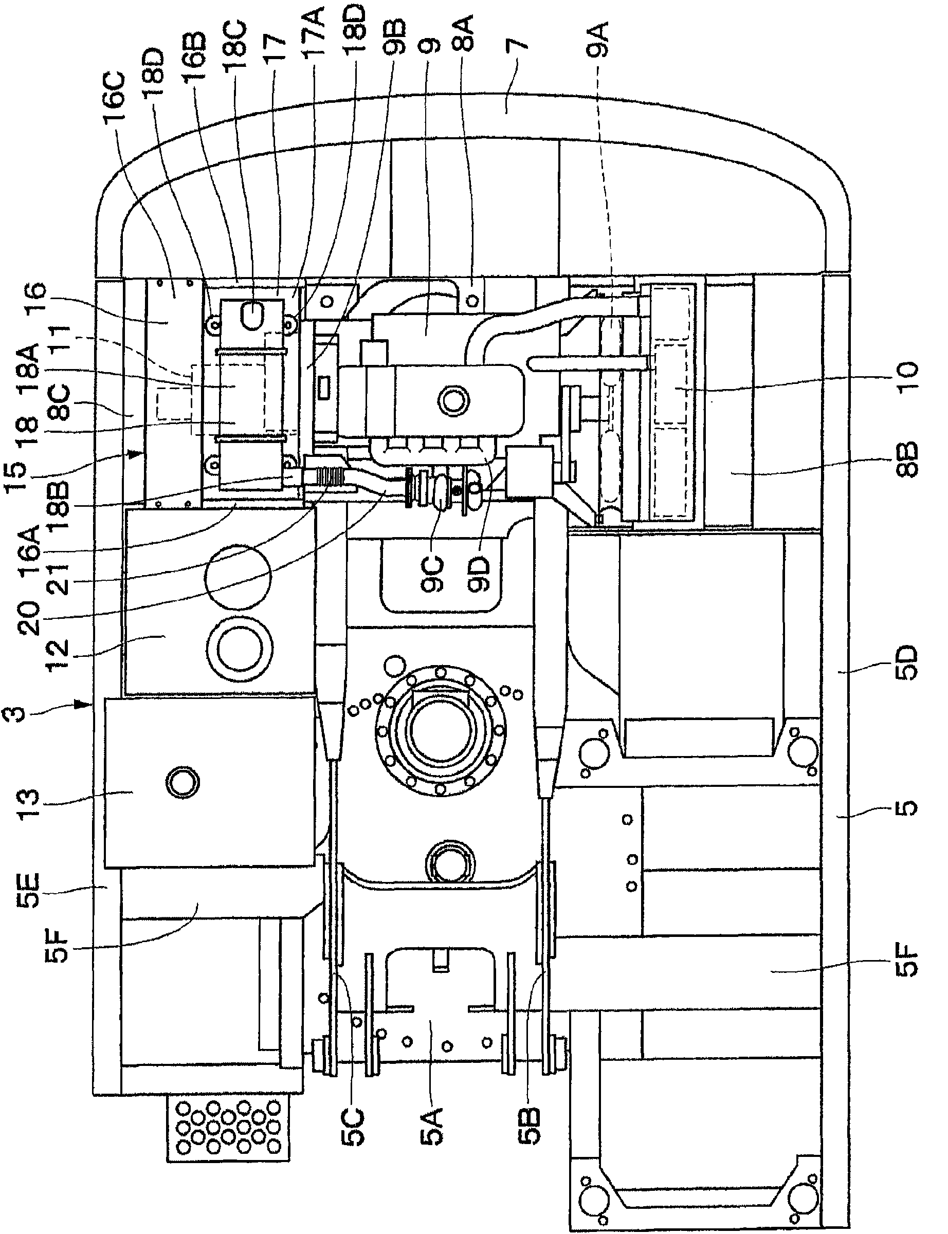
[0044] Here, the upper revolving body 3 constituting the hydraulic excavator 1 will be described in detail. I...


PUM


Abstract

The invention relates to construction machinery. An exhaust gas processing apparatus can be mounted on components different from an engine. A house component (16) is arranged around a hydraulic liquid pump (11); the house component (16) is provided with a shielding cover (17) that shields space between the engine (9) and the hydraulic liquid pump (11). In addition, a processing apparatus mountingportion (17A) for mounting the exhaust gas processing apparatus (18) is arranged on the shielding cover (17). The assembled sub assembly parts (15) are mounted on a whirl framework (5). Therefore, the exhaust gas processing apparatus (18) can be separated from a vibrating system of the engine (9), which prevents from transmission of vibration of the engine (9). In addition, the shielding cover (17) can be mounted before the exhaust gas processing apparatus (18) is connected to the engine (9), thereby configuring the shielding cover (17) by simple work without penetrating a narrow gap between the hydraulic liquid pump (11) and the exhaust gas processing apparatus (18).

Description

technical field [0001] The present invention relates to a construction machine such as a hydraulic excavator, and more particularly to a construction machine equipped with an exhaust gas treatment device for treating engine exhaust gas. Background technique [0002] In general, a hydraulic excavator as a representative example of construction machinery includes: a self-propelled undercarriage; an upper revolving body rotatably mounted on the undercarriage; Working device for tilting action. [0003] Furthermore, the upper revolving body roughly includes: a revolving frame constituting a support structure; a cab provided on the front side of the revolving frame for an operator to ride in; A hydraulic pump on one side in the longitudinal direction of the engine; an exhaust gas treatment device connected to the exhaust manifold of the above-mentioned engine through an exhaust exhaust pipe; and a house cover installed on the swing frame to cover these devices . [0004] Here,...

Claims


Application Information

Patent Timeline
IPC IPC(8): F01N7/00
Inventor 小林敬弘镰田博之安部敏博
Owner HITACHI CONSTR MASCH CO LTD
Why Eureka
Try Eureka