Soft alloy layer forming apparatus and soft alloy layer forming method

A technology of soft alloy and base metal, which is applied in the field of soft alloy layer formation device and soft alloy layer formation, and can solve problems such as the difficulty in predicting the adhesion strength between the base metal and the bearing metal layer, increased production costs, and dispersion of adhesion strength.

Inactive Publication Date: 2009-12-30
KK TOSHIBA
View PDF4 Cites 3 Cited by
  • Summary
  • Abstract
  • Description
  • Claims
  • Application Information

AI Technical Summary

Problems solved by technology

[0014] However, if the fine wire mesh is provided on the inner peripheral surface of the base metal by the above-mentioned conventional technique, it is difficult to provide the fine wire mesh in the vicinity of the sliding surface of the bearing metal layer which becomes the source of thermal fatigue and damage.
Therefore, it is difficult to expect to achieve the effect of avoiding thermal fatigue and damage in the bearing metal
In addition, there arises a problem that the production cost increases because it requires the step of setting and fixing the thin mesh wire
[0015] In addition, if the above conventional technique is used to irradiate laser light on the surface of the b

Method used


Image

  • Soft alloy layer forming apparatus and soft alloy layer forming method
  • Soft alloy layer forming apparatus and soft alloy layer forming method
  • Soft alloy layer forming apparatus and soft alloy layer forming method

Examples


no. 1 approach

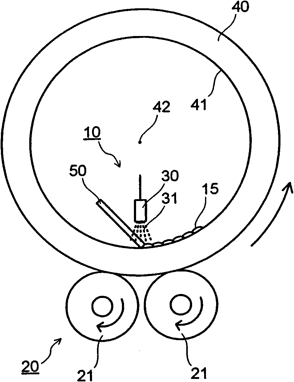
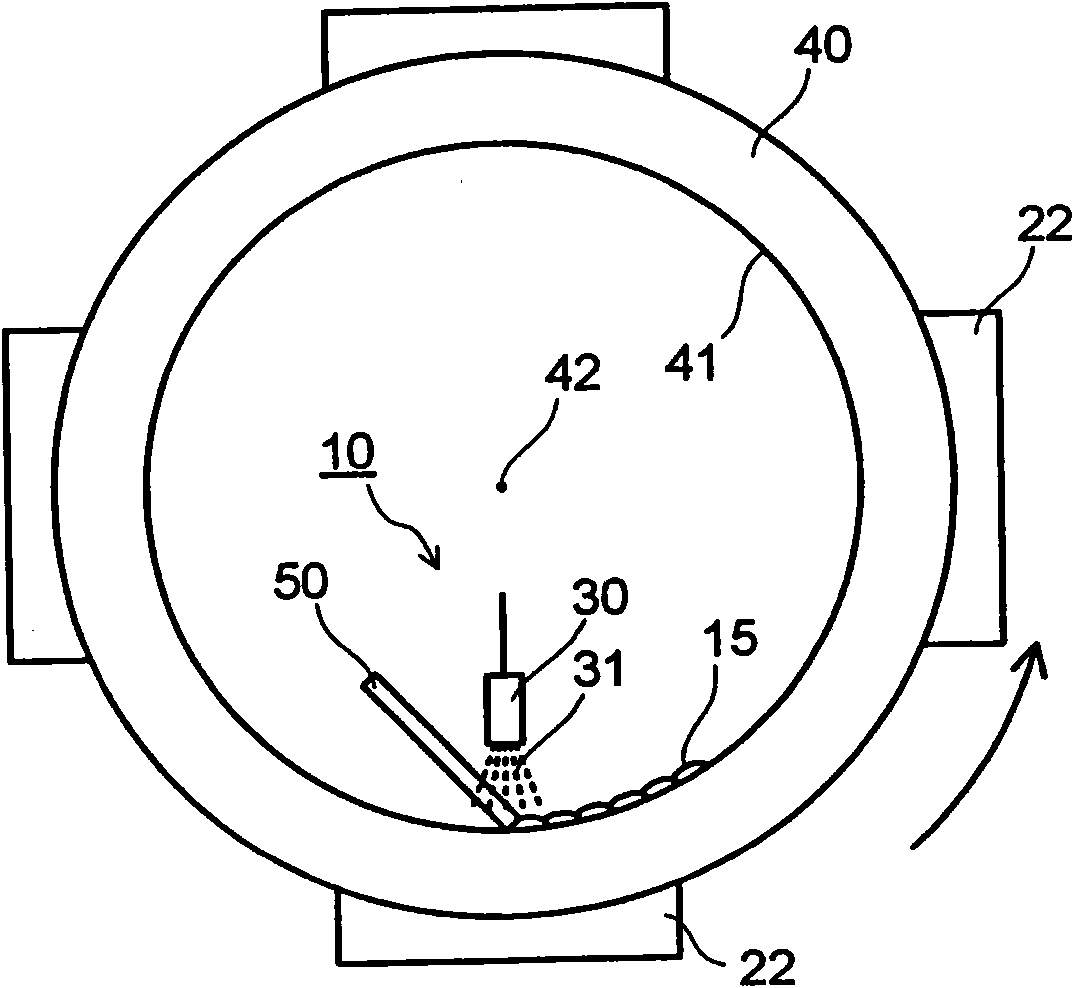
[0066] figure 1 The soft alloy forming apparatus 10 of the first embodiment of the present invention is schematically illustrated. Figure 2A and Figure 2B A soft alloy forming device 10 is schematically illustrated with a base metal support member 20 in another configuration. image 3A cross section of a base metal on which a soft alloy layer 15 is formed by the soft alloy layer forming apparatus 10 according to the first embodiment of the present invention is schematically shown. Figure 4 A cross-section of the interface between the base metal 40 and the soft alloy layer 15 is schematically illustrated.

[0067] The soft alloy layer forming device 10 is a device for forming a soft alloy layer 15 made of a soft alloy on the inner peripheral surface 41 of a base metal 40 made of an arc surface by a surfacing process, and the soft alloy layer slidably contacts with the rotor, For example turbine rotor contact. like figure 1 As shown in , the soft alloy layer forming ap...

no. 2 approach

[0087] Figure 5 A soft alloy layer forming apparatus 10 according to the second embodiment of the present invention is schematically illustrated. The soft alloy layer forming apparatus 10 of the second embodiment of the present invention provides the soft alloy forming apparatus 10 of the first embodiment of the present invention with a cooling gas injection unit 60 for injecting cooling gas to the soft alloy layer 15 and a cooling gas injection unit 60 for cooling the base metal. The base metal cooling unit 70 on the outer peripheral surface of 40 is constructed. Note that since the same components as those in the soft alloy layer forming apparatus of the first embodiment are assigned the same reference numerals, repeated descriptions are omitted or simplified.

[0088] like Figure 5 As shown in , the soft alloy layer forming apparatus 10 includes a base metal supporting member 20 , an arc generating unit 30 , a cooling gas injection unit 60 and a base metal cooling unit ...

Embodiment 1

[0103] In Example 1, a base metal 40 made of structural steel partially simulating a journal bearing having an inner diameter of 381 mm, an outer diameter of 481 mm and a center angle of 85° was prepared. Note that the method of forming the soft alloy layer is the same as that described in the first embodiment, so reference figure 1 Give the instructions below.

[0104] The base metal 40 is placed on the base metal supporting member 20, and the base metal is rotated while overlaying is completed from one end to the other in the direction of the rotation axis. Subsequently, the arc generating unit 30 is oscillated with an amplitude of 7 mm and a frequency of 3 Hz in the direction of the axis of rotation, where the axis of rotation is the base metal, and then a predetermined voltage is applied between the arc generating unit 30 and the base metal 40 to generate an arc 31 The central axis 42 of the inner periphery of the metal 40 . In addition, the welding current at this time...


PUM

PropertyMeasurementUnit
The average thicknessaaaaaaaaaa
Thicknessaaaaaaaaaa
Thicknessaaaaaaaaaa

Abstract

A soft alloy layer forming apparatus (10) includes a base metal support part (20) rotationally supporting a base metal (40) with a center axis (42) of an inner periphery of the base metal (40) being a rotation axis, and an arc generating unit (30) movable in a direction of the rotation axis of the inner periphery of the base metal (40), fixed at a predetermined distance from the inner peripheral face (41) of the base metal (40), and generating an arc (31) between itself and the base metal (40). While rotating the base metal (40) and maintaining the distance constant between the arc generating unit (30) and the inner peripheral face (41) of the base metal (40), a soft alloy member (50) is melted by the arc generating unit (30) to form a soft alloy layer (15) on the inner peripheral face (41) of the base metal (40). The invention also relates to a soft alloy layer forming method.

Description

[0001] Cross References to Related Applications [0002] This application is based upon and enjoys the benefit of priority from the prior Japanese Patent Application No. 2008-137366 filed on May 27, 2008 and the prior Japanese Patent Application No. 2009-099021 filed on April 15, 2009; The contents are incorporated herein by reference. technical field [0003] The present invention relates to a soft alloy layer forming device and a soft alloy layer forming method for forming a soft (mass) alloy layer. The soft alloy layer is related to a bearing for supporting a rotor etc. and is in slidable contact with the rotor. The soft alloy layer is also associated with a sealing member which is in contact with the rotor and seals off lubricating oil or steam, the aforementioned components being used in power (electricity) generating devices such as generators and (steam) turbines, the device and method being used in particular to form A soft alloy layer in slidable contact with the rot...

Claims


Application Information

Patent Timeline
IPC IPC(8): F16C33/14
Inventor 石渡裕青山和夫远藤伸昭田中清贵片山仁
Owner KK TOSHIBA
Why Eureka
Try Eureka