Gravity unloading mechanism for solar array ground experiment

A solar panel, gravity unloading technology, applied in the aerospace field, can solve the problems of unloading mechanism literature reports and other problems, and achieve the effect of reasonable arrangement, high reliability and good craftsmanship

Inactive Publication Date: 2009-12-30
BEIHANG UNIV +1
View PDF0 Cites 28 Cited by
  • Summary
  • Abstract
  • Description
  • Claims
  • Application Information

AI Technical Summary

Problems solved by technology

[0004] At present, there is no literature report a...

Method used


Image

  • Gravity unloading mechanism for solar array ground experiment
  • Gravity unloading mechanism for solar array ground experiment
  • Gravity unloading mechanism for solar array ground experiment

Examples


Embodiment Construction

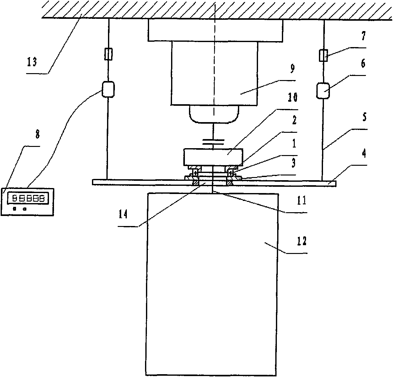
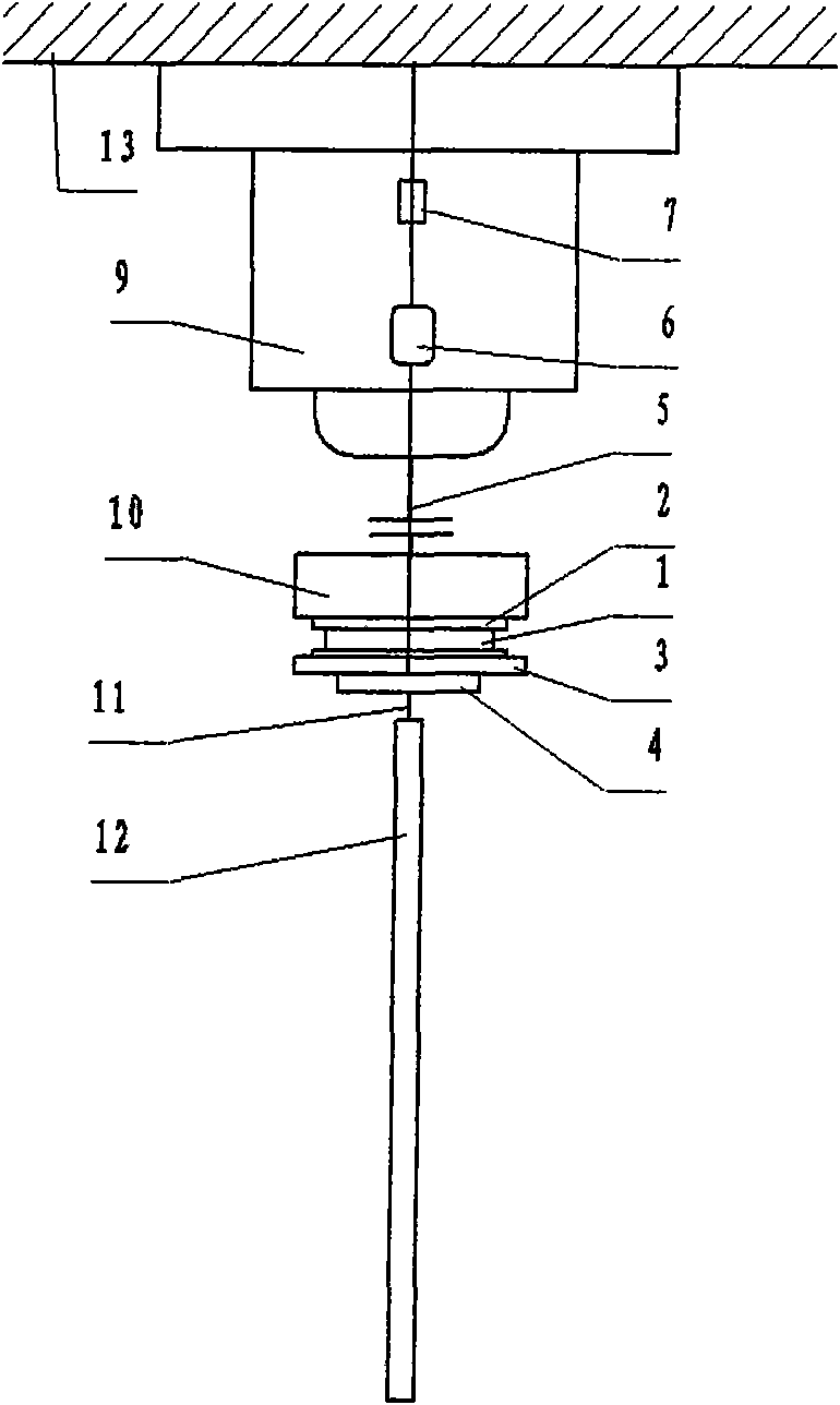
[0020] like figure 1 , 2 As shown, the solar sail panel in the gravity unloading mechanism of the solar sail panel ground experiment of the present invention includes a force-bearing part 10, a connecting rod 11 and a functional part 12, and the function of the force-bearing part 10 is to bear the driving force of the drive motor 9, and pass The connecting rod 11 is transmitted to the functional part 12, and the force-bearing part 10 and the connecting rod 11, and between the connecting rod 11 and the functional part 12 are connected by screws. The ground test gravity unloading mechanism consists of a thrust ball bearing 1, a bearing inner base 2, a bearing outer base 3, a beam 4, a steel cable 5, a pressure sensor 6, and a steel cable regulator 7.

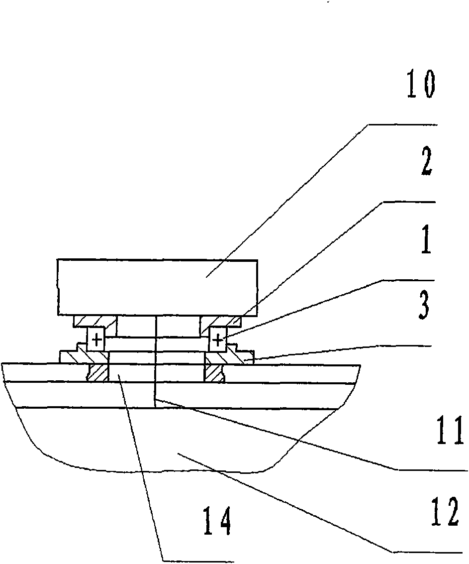
[0021] A through hole 14 is left between the bearing inner base 2 and the bearing outer base 3 , so that the connecting rod 11 between the load-bearing part 10 and the functional part 12 of the solar panel can pass through the th...


PUM


Abstract

The invention relates to a gravity unloading mechanism for solar array ground experiment, which comprises a thrust ball bearing, a bearing inner base, a bearing outer base, a cross beam, steel cables, pressure sensors and a display. The inner circle and the outer circle of the thrust ball bearing are respectively matched with the bearing inner base and the bearing outer base to form a moving component of an unloading mechanism; the bearing inner base is connected with the force bearing part of a solar array, and the bearing outer base is connected with the cross beam; the two ends of the cross beam are connected with the steel cables which are provided with the pressure sensors, and the two steel cables are hung on a mounting surface outside the system. The gravity of the solar array is transmitted to the external mounting surface through the bearing inner base, the thrust ball bearing, the cross beam and the steel cables, and is not born through a cavity driving motor any more, and simultaneously the free rotation can be guaranteed, therefore the mechanical environment that the driving motor provides torque for the solar array only and does not provide holding power for the solar array under zero gravity conditions can be simulated.

Description

technical field [0001] The invention relates to a gravity unloading mechanism for ground experiments of solar sail panels, which can be used in ground experiments of solar sail panels to eliminate the influence of gravity on system tests, and is mainly used in the aerospace field. Background technique [0002] Most of the current satellites have solar panels to provide energy for the electronic equipment on the star. In order to ensure the maximum efficiency of the solar panels and generate sufficient power, it is necessary to adjust the orientation of the solar panels according to the orbit and attitude of the satellite platform, so that the sunlight can be irradiated vertically as much as possible. This task is driven by a motor. In space, the solar panels are in a state of weightlessness, and the drive motor only provides torque to the solar panels without axial force or shear force. However, under ground conditions, due to the influence of gravity, when the sailboard is...

Claims


Application Information

Patent Timeline
IPC IPC(8): G01M19/00G01M99/00
Inventor 王志旺程伟杨彦龙付志超
Owner BEIHANG UNIV
Why Eureka
Try Eureka