Draw-ring type unlocking device for photoelectric module

A technology of unlocking device and photoelectric module, which is applied in the direction of optical waveguide coupling, etc., can solve the problems of frequent use of optical fiber connectors, shortening the service life of optical fiber connectors, and inability to apply them, achieving compact structure, high reliability, and prolonging life. Effect

Inactive Publication Date: 2009-12-30
WUHAN TELECOMM DEVICES
View PDF0 Cites 23 Cited by
  • Summary
  • Abstract
  • Description
  • Claims
  • Application Information

AI Technical Summary

Problems solved by technology

Generally, the unlocking device used in the plug-in connection method must be pulled out of the fiber optic connector before it can be unlocked, so that the fiber optic connector is used very frequently, which will shorten the service life of the fiber optic connector; the second type of lock is rarely used. In the unlocking mode of the unlocking device of the pigtail type connection, this cannot be applied in closely arranged system equipment

Method used


Image

  • Draw-ring type unlocking device for photoelectric module
  • Draw-ring type unlocking device for photoelectric module
  • Draw-ring type unlocking device for photoelectric module

Examples


Embodiment Construction

[0059] The working principle of the present invention is:

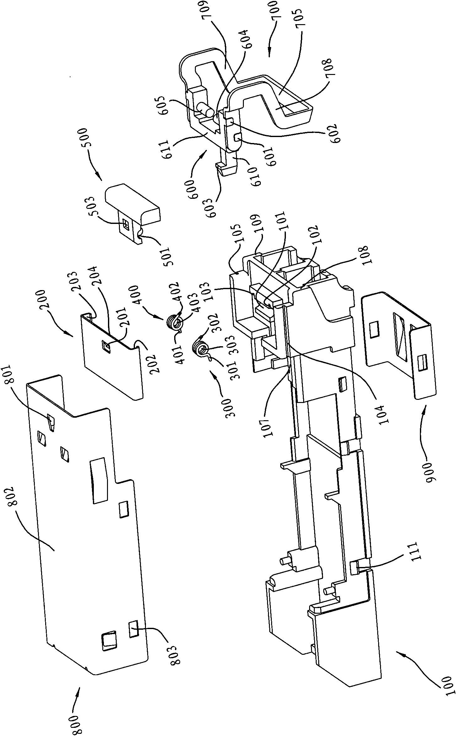
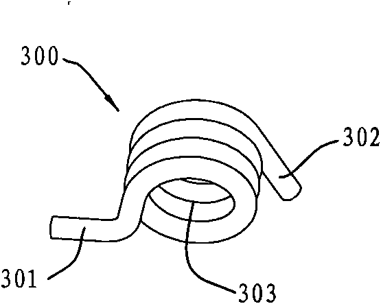
[0060] When the module is in the locked state, the first side surface of the pull ring is attached to the first end surface of the base, and the second side surface of the pull ring is attached to the second end surface of the base. Turn the pull ring, and the pull ring drives the brake pad to rotate together. When the guide rod of the brake pad touches the platform of the base, the pull ring and the brake pad stop rotating together. At this time, the lock on the brake pad has rotated to the upper surface of the outer cover. Below, the module is unlocked. Loosen the pull ring, because the brake pad is subjected to the torsion force of the right-handed torsion spring and the left-hand torsion spring, the pull ring is driven to rotate until it returns to the initial position.

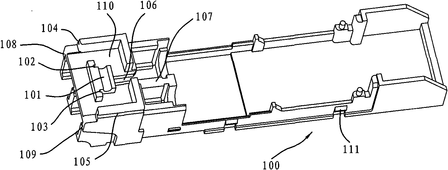
[0061] Below in detail in conjunction with drawings and embodiments: the present invention includes a base 100, a cover plate 200, a right-hand...


PUM


Abstract

The invention discloses a draw-ring type unlocking device for a photoelectric module. The device comprises a base, a right-handed torsion spring, a left-handed torsion spring, a brake pad, a draw ring and an outer cover, wherein the middle part of the right-handed torsion spring is provided with a round hole; one end of the right-handed torsion spring is provided with a bending leg, while the other end is provided with a stopping leg; the middle part of the left-handed torsion spring is provided with a round hole; one end of the left-handed torsion spring is provided with a bending leg, while the other end is provided with a stopping leg; the base is provided with a semi-circular groove, and the semi-circular groove is provided with a limitation groove matched with the torsion spring stopping legs; the round holes of the torsion springs are sleeved on the rotary shaft on the inner side of the brake pad; the brake pad is provided with a clipping groove matched with the bending legs of the torsion springs and a protruding platform matched with the groove corresponding to the draw ring; and the base is connected with a clipping plate which is provided with a concave pit matched with springs on the upper surface of a cover plate. The device can be conveniently assembled and disassembled completely by a brake device arranged in the module; the assembly of the draw ring is easy, the reliability is high, the draw ring possesses the automatic reset function, and the manual reset is unnecessary; the device can be used as a tail optical fiber type device as well as a plugging type device, and when used as the plugging type device, the device can realize the unlocking under the condition of not pulling out an optical fiber connector, so that the service life of the optical fiber connector is effectively prolonged.

Description

technical field [0001] The invention relates to an unlocking device for a photoelectric module in the field of optical communication, in particular to a ring-type unlocking device for a photoelectric module. Background technique [0002] Currently, SFP (Small Form-factor Pluggables, Chinese name: Small Form-factor Pluggables) optical fiber connection methods mainly include plug-in type and pigtail type. There are two types of unlocking devices for plug-in connection and pigtail connection: push-pull and ring-pull. There are two main unlocking methods: the first is that the brake pad lifts up the cage's lock shrapnel to unlock; the second is The second method is to unlock the lock by lowering the latch with locking function on the module case below the upper surface of the case. [0003] At present, the common unlocking devices are seldom capable of being used for both plug-in and pigtail connection. Generally, the unlocking device used in the plug-in connection method must...

Claims


Application Information

Patent Timeline
Patent Type & Authority Applications(China)
IPC IPC(8): G02B6/42
Inventor 宋蓓莉全本庆徐红春周芸
Owner WUHAN TELECOMM DEVICES
Why Eureka
Try Eureka