Peak sampling hold circuit, peak sampling hold method and application

A peak sampling and holding circuit technology, applied in electrical analog memory, static memory, instrument, etc., can solve the problem that the output voltage cannot reproduce the input signal voltage well, and achieve the effect of enhancing the load driving ability and avoiding charge accumulation

Inactive Publication Date: 2012-04-11
HANGZHOU SILAN MICROELECTRONICS
View PDF5 Cites 0 Cited by
  • Summary
  • Abstract
  • Description
  • Claims
  • Application Information

AI Technical Summary

Problems solved by technology

[0009] The disadvantage of the existing sample-and-hold circuit is that when the hold switch 16 is turned on and the sample switch 13 is not turned on, the charge on the sampling capacitor will flow to the hold capacitor 18 to charge the hold capacitor until the charge on the sample capacitor 15 The charging of the holding capacitor is completed only when the voltage is equal to the voltage on the holding capacitor, so that the final result is that the voltage on the holding capacitor is the voltage when the sampling capacitor 15 and the holding capacitor 18 are balanced, not the voltage of the input line 11, the output voltage Does not reproduce the voltage of the input signal well

Method used


Image

  • Peak sampling hold circuit, peak sampling hold method and application
  • Peak sampling hold circuit, peak sampling hold method and application
  • Peak sampling hold circuit, peak sampling hold method and application

Examples


Embodiment Construction

[0063] The content of the present invention will be further described below in conjunction with the accompanying drawings.

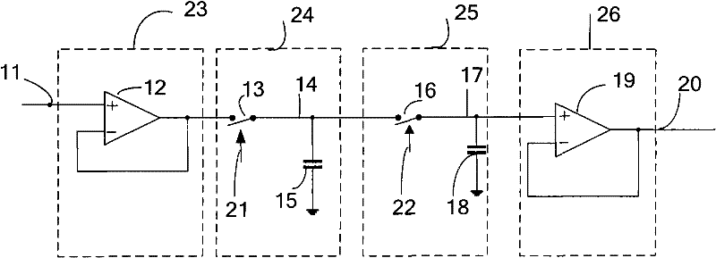
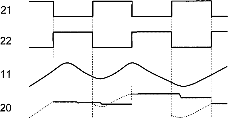
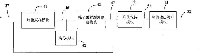
[0064] peak sample-and-hold circuits, such as Figure 4 As shown, it includes a peak sampling module 41, a peak sampling buffer output module 43, a peak hold module 44, a peak output buffer module 45 and a clearing module 42, such as Figure 4 , 7 , as shown in 8:

[0065] The peak sampling module 41 samples the peak voltage 46 of each time point of the input signal 37;

[0066] The peak sampling buffer output module 43 follows the peak voltage 46, and enhances the load driving capability of the peak voltage 46;

[0067] The peak holding module 44 holds the voltage 47 output by the peak sampling buffer output module 43;

[0068] The peak output buffer module 45 enhances the output load driving capability of the peak hold module 44;

[0069] The clearing module 42 clears the peak voltage of the previous cycle output by the peak sampling module 41 to ...


PUM


Abstract

The invention discloses a peak sampling hold circuit and a peak sampling hold method. The peak sampling hold circuit comprises a peak sampling module, a peak sampling buffer input module, a peak hold module, a peak output buffer module and a zero clearing module; the peak sampling module samples peak voltage of all time points of input signals; the peak sampling buffer output module follows the peak voltage and enhances load driving capability of the peak voltage; the peak hold module holds the voltage output by the peak sampling buffer output module; the peak output buffer module enhances the output load capability of the peak hold module; the zero clearing module carries out clearing in time to peak voltage of last period output by the peak sampling module after the peak hold module outputs voltage so as to be convenient to carry out peak sampling in next period. The peak sampling hold circuit and a peak sampling hold method can better reappear the peak of the input signal and can apply the peak sampling hold circuit to a power system.

Description

technical field [0001] The invention relates to a peak sampling and holding technology, in particular to a peak sampling and holding circuit in a computer power supply system and its application. Background technique [0002] In a power supply system, the magnitude of the input voltage is an important factor that determines whether the system can work normally, so it is necessary to sample the line voltage through sample and hold. figure 1 It is the circuit diagram of the existing sample and hold circuit. The sample and hold circuit includes: an input buffer module 23 , a sample module 24 , a hold module 25 and an output buffer module 26 . [0003] The input buffer module 23 includes a follower composed of an operational amplifier 12 , the positive input terminal of the follower is connected to the input signal line 11 , and the negative terminal of the follower is connected to the output. [0004] Described sampling module 24 comprises the control line 21 of sampling swit...

Claims


Application Information

Patent Timeline
Patent Type & Authority Patents(China)
IPC IPC(8): G11C27/02
Inventor 王文建姚云龙
Owner HANGZHOU SILAN MICROELECTRONICS
Why Eureka
Try Eureka