Device for determining clogging of reducing agent path and method of determining clogging of reducing agent path

一种堵塞判定、还原剂的技术,应用在排气处理装置的诊断装置、消音装置、排气装置等方向,能够解决效率恶化等问题,达到减少部件个数、实现保养作业的效果

Active Publication Date: 2009-12-30
BOSCH CORP
View PDF1 Cites 29 Cited by
  • Summary
  • Abstract
  • Description
  • Claims
  • Application Information

AI Technical Summary

Problems solved by technology

[0007] Additionally, when a blockage occurs in either the supply line or the return line of the reductant, if it is unclear in which line the blockage occurs, the results must be checked or Repair and replacement of each line may deteriorate efficiency

Method used


Image

  • Device for determining clogging of reducing agent path and method of determining clogging of reducing agent path
  • Device for determining clogging of reducing agent path and method of determining clogging of reducing agent path
  • Device for determining clogging of reducing agent path and method of determining clogging of reducing agent path

Examples


no. 1 Embodiment approach

[0038] 1. Blockage determination device for reducing agent path

[0039] (1) The overall composition of the exhaust purification system

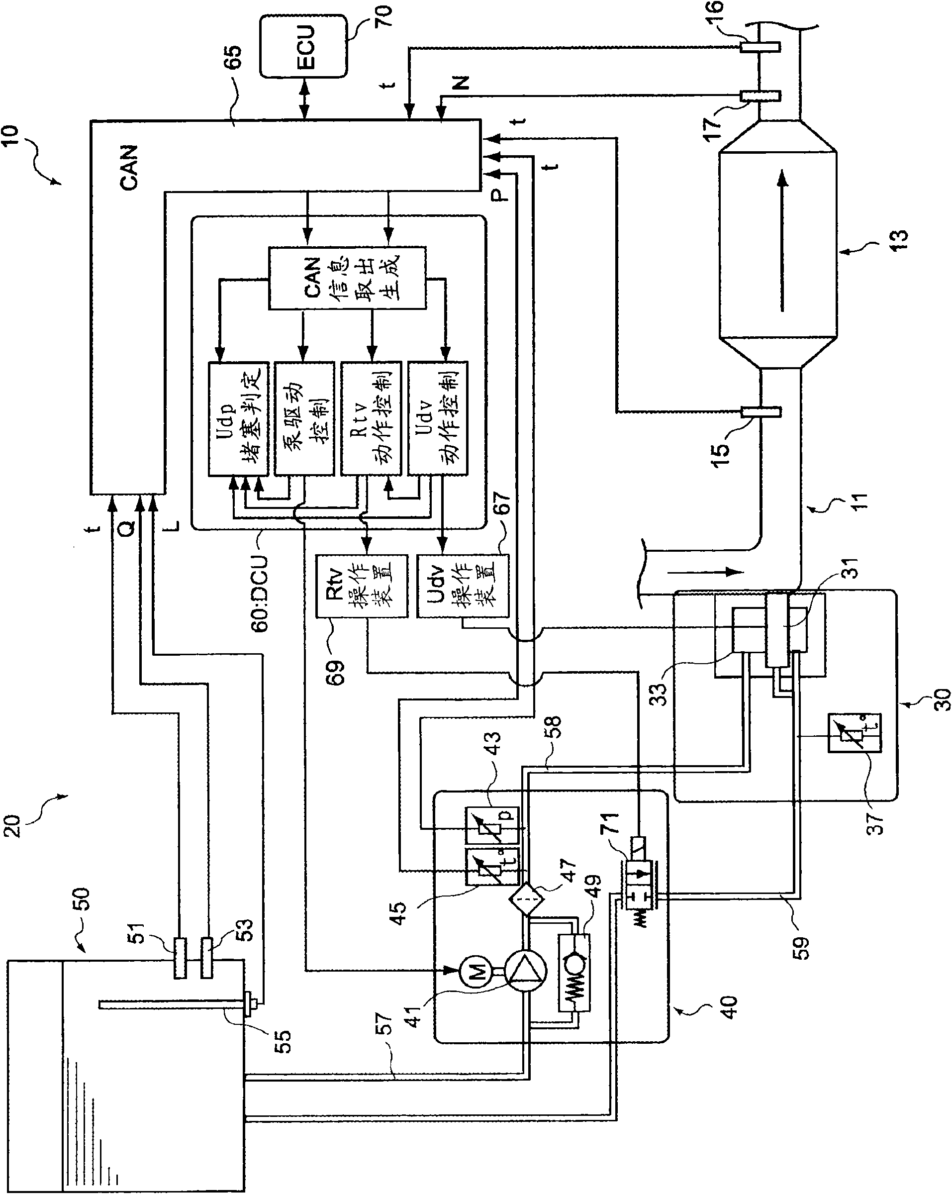
[0040] First, refer to figure 1 A configuration example of an exhaust gas purification system (hereinafter, sometimes referred to as a "system") provided with a reducing agent passage clogging determination device according to this embodiment will be described.

[0041] figure 1 In the exhaust gas purification system 10 shown, an aqueous urea solution is used as a reducing agent, and the exhaust gas is passed through NO with the reducing agent. x Catalyst 13 to selectively reduce NO x . This exhaust gas purification system 10 is disposed in the middle of an exhaust passage 11 connected to the internal combustion engine, and has a reducing agent supply device 20 having a function for selectively reducing NO contained in the exhaust gas. x NO x Catalyst 13, and in NO x The upstream side of the catalyst 13 is used for a reducing agent ...

no. 2 Embodiment approach

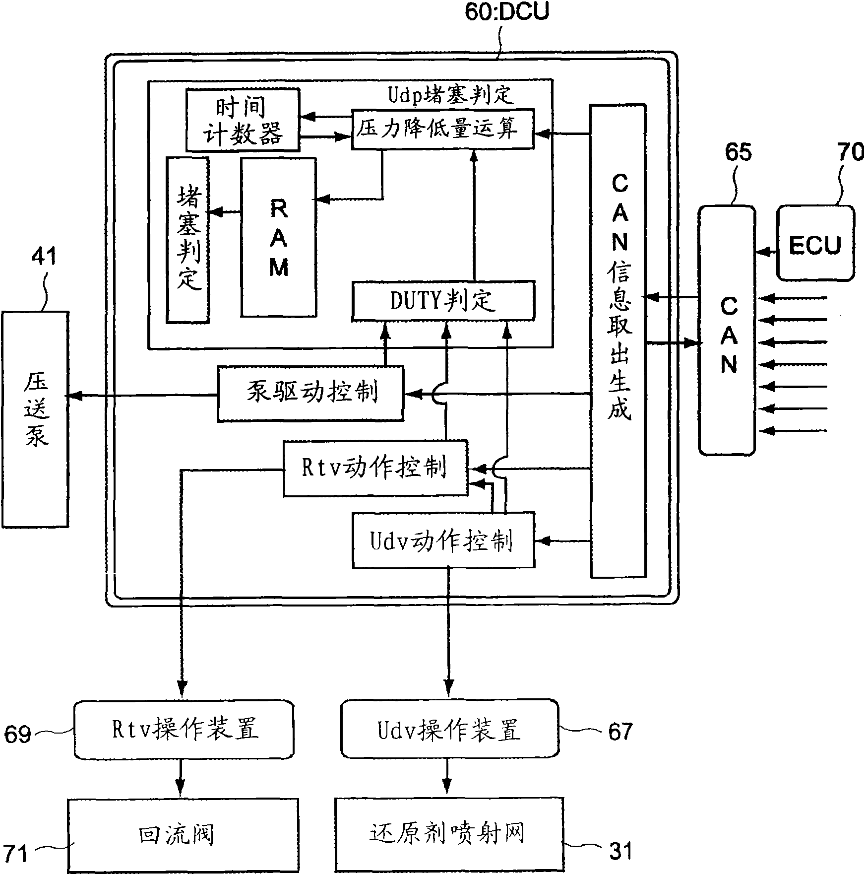
[0087] 1. Blockage determination device for reducing agent path

[0088] Figure 4 A configuration example of an exhaust gas purification system (hereinafter, sometimes simply referred to as a "system") provided with a reducing agent passage clogging determination device according to this embodiment is shown.

[0089] Should Figure 4 The exhaust gas purification system 100 shown is designed with holes 35 so that instead of the figure 1 The illustrated exhaust purification system 10 of the first embodiment has a recirculation valve 71 in the circulation path 59 .

[0090] That is, the injection unit 30 in the exhaust purification system 100 of the present embodiment has: a storage chamber 33 for storing the reducing agent pumped from the pump unit 40 side; and a reducing agent injection valve 31 connected to the storage chamber 33 The hole 35 is arranged in the middle of the path leading from the storage chamber 33 to the circulation path 59 ; the temperature sensor 37 is ...

no. 3 Embodiment approach

[0103] 1. The overall composition of the exhaust purification system

[0104] Compared with the exhaust purification system of the first embodiment, the exhaust purification system having the clogging determination device of the reducing agent passage of the present embodiment differs in the configuration of the reducing agent passage in the reducing agent supply device.

[0105] Figure 6 A configuration example of the exhaust purification system 110 of the present embodiment is shown, and components other than the reducing agent supply device 120 are the same as those of the exhaust purification system of the first embodiment.

[0106] The reductant supply device 120 included in the exhaust purification system 110 of this embodiment includes: a reductant injection valve 131; a storage container 150 for storing the reductant; a pump assembly 140 for pumping the reductant in the storage container 150 to the reducing The pump 141 of the agent injection valve 131 ; and the DCU ...


PUM


Abstract

A device for determining clogging of a reducing agent path and method of determining clogging of reducing agent path, which, when there is clogging at any position in both a supply line and a return line, accurately detects the clogging and estimates the position of the clogging. The device for determining clogging of a reducing agent path has pump drive control means for performing DUTY control of a pump so that a pressure value is maintained at a predetermined level; drive DUTY determination means for determining whether a drive DUTY of the pump is less than a predetermined threshold corresponding to the degree of opening of a reducing agent injection valve; pressure reduction amount calculation means which, when the drive DUTY of the pump is determined to be less than the threshold, stops the pump, fully opens the reducing agent injection valve, and then calculates a pressure reduction amount detected by a pressure sensor and representing the amount of reduction in pressure in a predetermined time; and clogging determination means for determining, based on the pressure reduction amount calculated by the pressure reduction amount calculation means, whether there is clogging in a first reducing agent path or a second reducing agent path.

Description

technical field [0001] The present invention relates to a clogging judging device and a clogging method of a reducing agent path in an exhaust purification system. In particular, it relates to a clogging determination device for a path in an exhaust purification system having a return path for keeping a reducing agent at a low temperature, and a clogging determination method for a reducing agent path. Background technique [0002] Conventionally, nitrogen oxides (hereinafter referred to as NO x ). as for purifying the NO x It is known that urea solution is sprayed and mixed into the exhaust gas as a reducing agent and selectively reduced and purified by a catalyst. x Exhaust purification system (SCR system). [0003] Here, when a urea solution is used as a reducing agent, the urea solution is hydrolyzed and crystallized when the temperature falls within a predetermined range, and clogging may occur in the reducing agent supply path and injection nozzle. Therefore, it is...

Claims


Application Information

Patent Timeline
Patent Type & Authority Applications(China)
IPC IPC(8): F01N3/18B01D53/86B01D53/94F01N3/04F01N3/08F01N3/28
CPCB01D2257/404F01N2550/05Y02T10/24Y02T10/47F01N3/2066F01N11/00B01D2251/2067F01N2610/14F01N2610/02Y02T10/12Y02T10/40B01D53/86B01D53/94F01N3/04F01N3/08
Inventor 北泽英一
Owner BOSCH CORP
Why Eureka
Try Eureka