Orderly glue stock kneader

A kneader and rubber technology, which is applied in the direction of mixers, mixers with rotating stirring devices, dissolution, etc., can solve problems such as short service life, chains affecting power transmission, and poor sealing performance, so as to improve service life and seal Good effect, easy to transport

Active Publication Date: 2010-01-06
YANTAI HUAPENG MACHINERY
View PDF2 Cites 5 Cited by
  • Summary
  • Abstract
  • Description
  • Claims
  • Application Information

AI Technical Summary

Problems solved by technology

The disadvantage of this double-layer structure is: firstly, when the mixing blade of the lower mixing tank is maintained, the upper mixing tank needs to be removed from the lower mixing tank, and then the mixing blade in the lower mixing tank can be repaired, because The equipment is relatively large, and this maintenance method is time-consuming and laborious, and the operation is difficult
Secondly, the agitating paddle shafts of the upper and lower mixing tanks are connected by sprocket and chain transmission, and the upper and lower agitating paddle shafts can only move synchronously, and cannot achieve separate mixing of the upper or lower mixing knives. The operation is not flexible, which brings certain limitations to production.
On the other hand, since the tension of the chain cannot be adjusted, the normal power transmission will be affected when the chain is too loose.
Third, the blanking door adopts an inverted V-shaped hydraulic sliding door. The structure of this sliding door has poor sealing performance and material leakage will occur.
The existing mixing blades are severely worn by materials, especially the stirring blades of the upper pot body, which are worn at high speed at high temperature and have a short service life

Method used


Image

  • Orderly glue stock kneader
  • Orderly glue stock kneader
  • Orderly glue stock kneader

Examples


Embodiment Construction

[0045] The present invention will be further described below with reference to the drawings and embodiments.

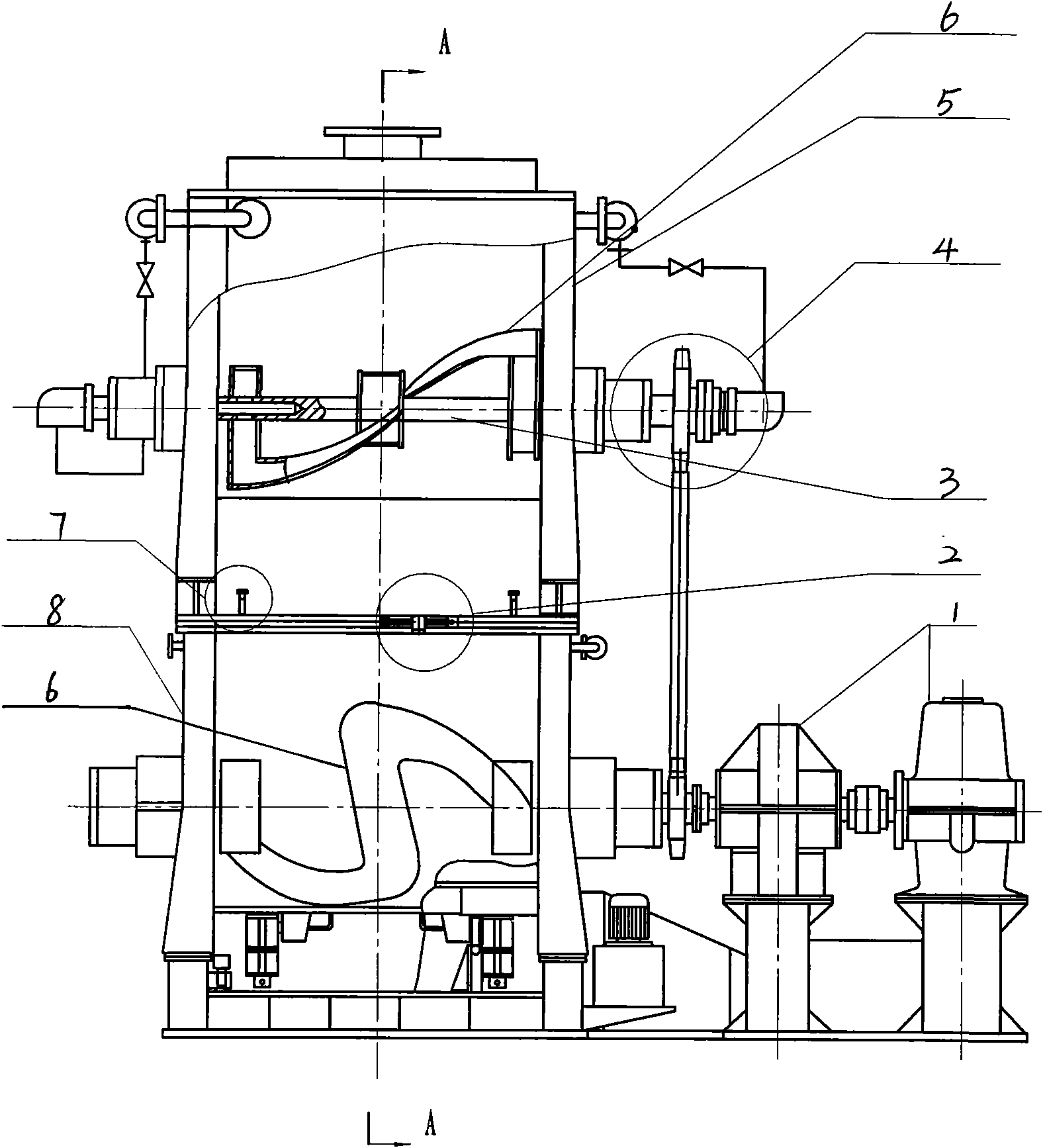
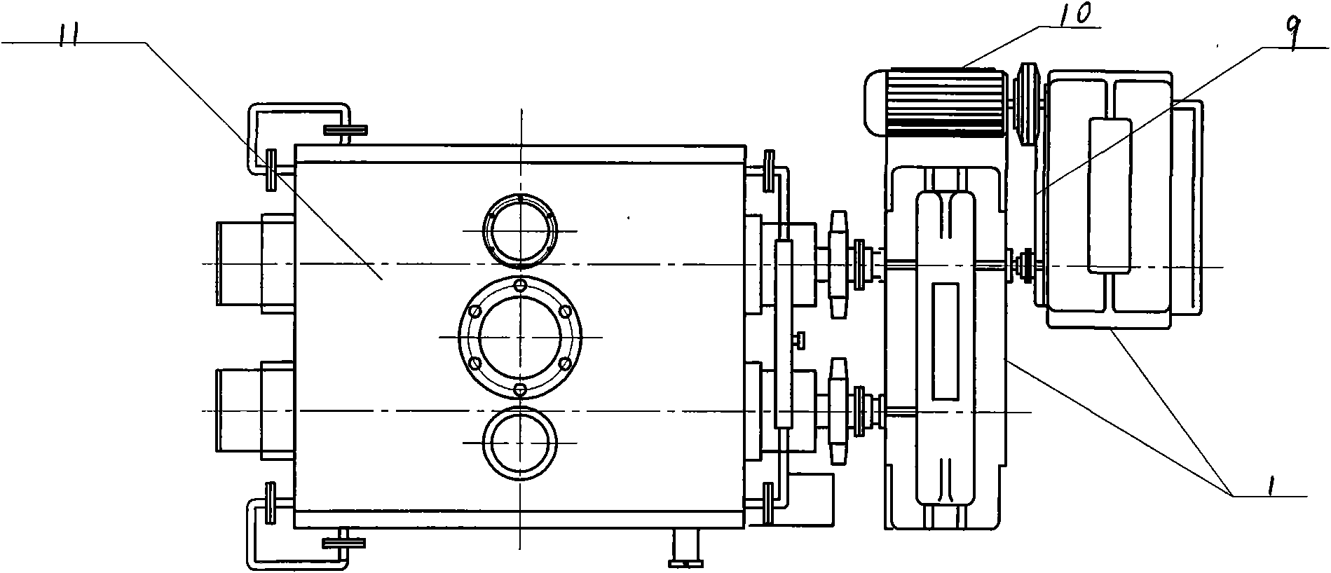
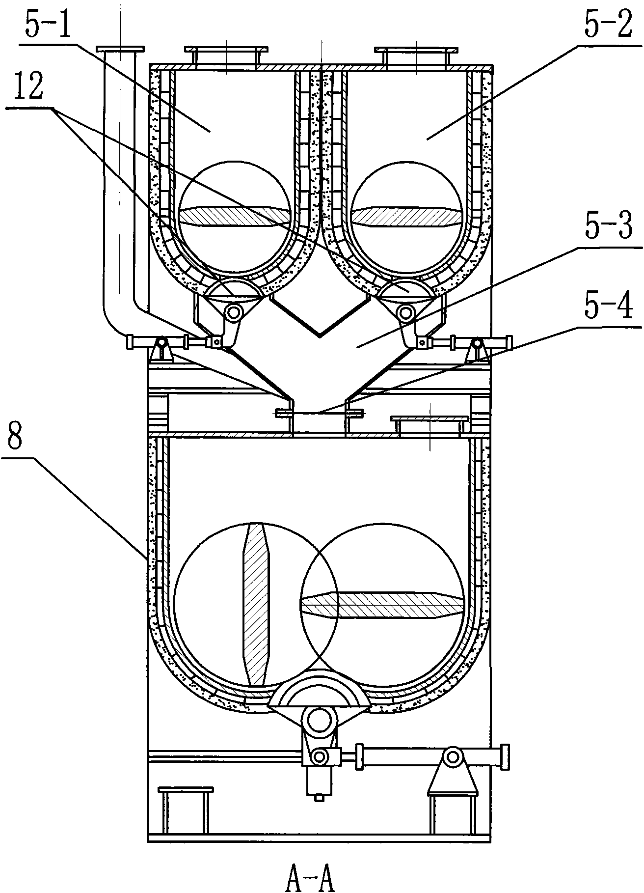
[0046] Such as figure 1 , 2 3, this example includes a transmission part 9 and a pot body part 11. The pot body part 11 is composed of an upper pot body 5 with a stirring knife 6 inside and a lower pot body 8 with a stirring knife 6 inside. Layer structure.

[0047] Among them, the upper pot body 5 has two parallel-installed first divided pot bodies 5-1 (powder divided pot bodies) and second divided pot bodies 5-2 (aggregate divided pot bodies). The first divided pot body 5-1, the second divided pot body 5-2 and the lower pot body 8 are equipped with a stirring knife 6 through a stirring knife shaft 3, respectively. An upper discharge system 12 is provided below the bottom discharge opening of the first divided pot body 5-1 and the second divided pot body 5-2, respectively, and the first divided pot body 5-1 and the second divided pot body 5-2 are discharged at the bottom...


PUM


Abstract

The invention relates to an orderly glue stock kneader which is structured in the following manner: an upper pot body (5) is arranged on the upper surface of a lower pot body (8) through a slideway of the bottom surface thereof, a slideway is arranged on the combining surface of the upper pot body and the lower pot body, a steel ball rolls on the slideway when the upper pot body is moved; a mobile maintenance mechanism (2) is arranged between the upper pot body and the lower pot body; the mobile maintenance mechanism (2) comprises a fixing support (21) the lower end of which is fixed on the lower pot body (8) and a mobile support (17) which is fixed on the upper pot body (5), the upper end of the fixing support (21) is provided with a driving mechanism which drives the upper pot body (5) to move on the lower pot body (8) in a horizontal direction, the outer end of a driving rod of the driving mechanism is connected with the mobile support (17), the mobile maintenance mechanism is arranged between the upper pot body and the lower pot body; the upper pot body can be moved away from the lower pot body by the mobile maintenance mechanism when a reamer in the lower pot body needs repairing.

Description

(1) Technical field [0001] The invention relates to a kneader, specifically an ordered rubber compound kneader. (2) Background technology [0002] The kneader is a special kneading equipment for carbon and electrode production. However, the existing kneader has the inconvenient maintenance of the stirring knife of the lower pot body, the transmission structure is not ideal, and the unreasonable design of the discharge door structure; the heating system of the stirring knife is easy to appear Problems such as oil leakage. [0003] The Chinese patent with the patent number 200620011200.8 discloses a powder and aggregate separate preheating stirring, three heating and three stirring rubber compound kneader. Its structural feature is that it adopts a double-layer structure, that is, an upper mixing tank is set on the upper part of the lower mixing tank; The stirring paddle shaft of the stirring tank is drivingly connected with the stirring paddle shaft of the lower mixing tank through...

Claims


Application Information

Patent Timeline
Patent Type & Authority Applications(China)
IPC IPC(8): B01F7/08B01F13/10B29B7/10B29B7/74
Inventor 王世乃王毅
Owner YANTAI HUAPENG MACHINERY
Why Eureka
Try Eureka