Hydro-pneumatic suspension control loop, multi-axle vehicle hydro-pneumatic suspension system and crane

A technology of oil and gas suspension and control loop, applied in suspension, elastic suspension, vehicle components, etc., can solve the problems of inability to apply rigid suspension system operating conditions, inability to perform lifting adjustment, low roll stiffness, etc. Improved maneuverability, large roll stiffness, improved safety effects

Active Publication Date: 2010-01-06
XUZHOU HEAVY MASCH CO LTD
View PDF0 Cites 39 Cited by
  • Summary
  • Abstract
  • Description
  • Claims
  • Application Information

AI Technical Summary

Problems solved by technology

However, the existing oil-pneumatic suspension only has the function of an elastic suspension, which cannot be applied to the operating conditions that require a rigid suspension system, such as: the heavy-duty driving condition of an engineering crane; in addition, there are still vehicles using the existing oil-pneumatic suspension Such a problem, the height of the vehicle body is fixed and cannot be adjusted for lifting; at the same time, the roll stiffness of the existing oil-pneumatic suspension is small, and the safety of the vehicle when driving on a curve is low

Method used


Image

  • Hydro-pneumatic suspension control loop, multi-axle vehicle hydro-pneumatic suspension system and crane
  • Hydro-pneumatic suspension control loop, multi-axle vehicle hydro-pneumatic suspension system and crane
  • Hydro-pneumatic suspension control loop, multi-axle vehicle hydro-pneumatic suspension system and crane

Examples


Embodiment Construction

[0040] The present embodiment will be described in detail below in conjunction with the accompanying drawings.

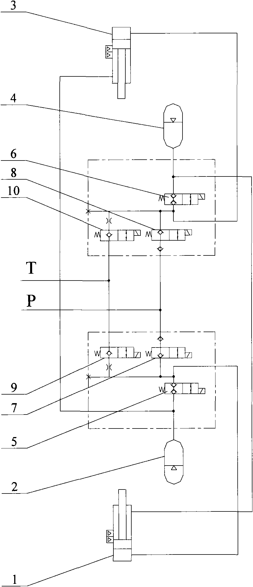
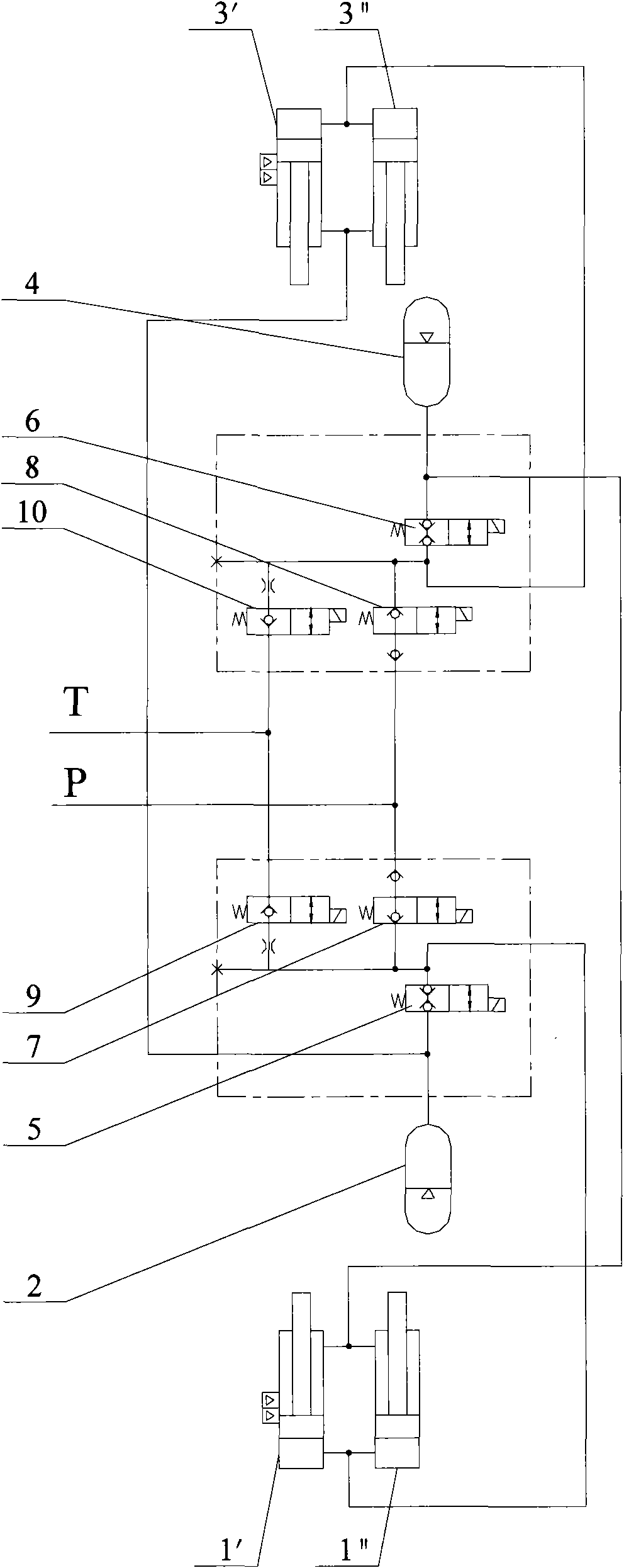
[0041] See figure 2 , which is a schematic diagram of the oil-pneumatic suspension control circuit provided by the present invention.

[0042] As shown in the figure, the control circuit of the hydropneumatic suspension provided by the present invention includes a left suspension cylinder 1, a left accumulator 2, a right suspension cylinder 3, a right accumulator 4, and a left suspension cylinder flexible and rigid control valve 5 and the right suspension oil cylinder flexible rigid control valve 6, the oil port of the left accumulator 2 communicates with the rodless cavity of the left suspension oil cylinder 1; the oil port of the right accumulator 4 communicates with the right suspension oil cylinder 3 The rodless cavity is connected; the left suspension oil cylinder flexible and rigid control valve 5 is installed in the passage between the left suspension oil c...


PUM


Abstract

The invention discloses a hydro-pneumatic suspension control loop. The design key point of the invention comprises that: a communication relationship between a suspension oil cylinder rodless cavity and an energy accumulator at the same side is controlled by a two position two-way valve to realize rigid and flexible conversion of a suspension system; each suspension oil cylinder rod cavity is communicated with an energy accumulator at the opposite side so as to obtain relatively strong side tilting rigidity; and communication relationships between a pressure oil line and the suspension oil cylinder rodless cavity and between an oil return oil line and the suspension oil cylinder rodless cavity are controlled by a two position two-way valve, respectively so as to control the lifting of a vehicle body. In the multi-axle vehicle hydro-pneumatic suspension system provided by the invention, all the middle axle hydro-pneumatic suspension control loops and rear axle hydro-pneumatic suspension control loops form a lifting control group so as to level the vehicle body. The hydro-pneumatic suspension control loop provided by the invention has reasonable and reliable design and higher comprehensive performance of the suspension system, and is suitable for a multi-axle vehicle, particularly for a multi-axle construction crane. The invention also provides a crane using the hydro-pneumatic suspension control loop.

Description

technical field [0001] The invention relates to vehicle suspension technology, in particular to an oil-air suspension control circuit, a multi-axis vehicle oil-air suspension system with the circuit and a crane using the oil-air suspension system. Background technique [0002] The suspension system connects the frame and the axle elastically to transmit the force and moment acting between the wheel and the frame, and to buffer the impact force transmitted from the uneven road to the frame or body, and to attenuate the vibration caused by it. , to ensure that the vehicle can run smoothly. [0003] Known vehicle suspension has two major categories of leaf spring suspension and oil-pneumatic suspension. Among them, the elastic characteristics of the leaf spring type suspension are linear, which cannot meet the requirements of high ride comfort and handling stability. The oil-pneumatic suspension has variable stiffness characteristics, which can not only improve the ride comfo...

Claims


Application Information

Patent Timeline
Patent Type & Authority Applications(China)
IPC IPC(8): B60G17/00B60G15/00
Inventor 史先信陈卫东刘东宏赵斌丁宏刚朱长建曹培雷贾宏飞
Owner XUZHOU HEAVY MASCH CO LTD
Why Eureka
Try Eureka