Sealing part assembly

A seal and assembly technology, applied in the field of water pump seal assembly structure, can solve the problems of difficult to get a perfect combination, the sealing end face is not tight, affecting the normal elastic value of the seal, etc., to achieve a high degree of assembly automation, Reliable sealing performance and simple manufacturing process

Inactive Publication Date: 2010-01-06
江雪忠
View PDF1 Cites 3 Cited by
  • Summary
  • Abstract
  • Description
  • Claims
  • Application Information

AI Technical Summary

Problems solved by technology

[0003] The main structure of the traditional seal assembly adopts the spring thrust to compress the end face contact seal between the moving ring body and the static ring body. There are three structural forms, but it is difficult to get a perfect combination of these three types of springs while combining the compensation force and the compensation amplitude.
Therefore, the thrust of the spring in the dynamic seal assembly presses the contact seal between the two ends of the dynamic ring body and the static ring body. Under the fluctuation of the peak value of rotation, the compensation force formed by the balance force difference of the spring has an impact on the seals on both ends of the medium. Medium impurities easily invade the end face and directly damage the end face, thus causing the seal failure phenomenon caused by the end face penetrating the medium leakage. In addition, when the rotation peak frequency changes greatly, a kind of vibration frequency generated on the sealing end face is easy to cause the sealing end face to be not tight. phenomenon, and when the vibrating force and the balance force conflict with each other, a twisting and destructive force is formed
[0004] In addition, the traditional structural design of the rubber sealing sleeve in the seal assembly structure has the characteristics of compression force along with the action of the spring. Since the compression force and the spring are mixed to form a mixed elastic value, the stability of the initial value sometimes affects the initial value of the seal. The normal elastic value is exerted during work, so the stability of the elastic value is also an important combination element for the collaborative sealing requirements of the seal assembly
[0005] Therefore, it is necessary to provide solutions to the above problems and apply new technologies to solve the cooperative sealing problem of the seal assembly structure

Method used


Image

  • Sealing part assembly
  • Sealing part assembly
  • Sealing part assembly

Examples


Embodiment 1

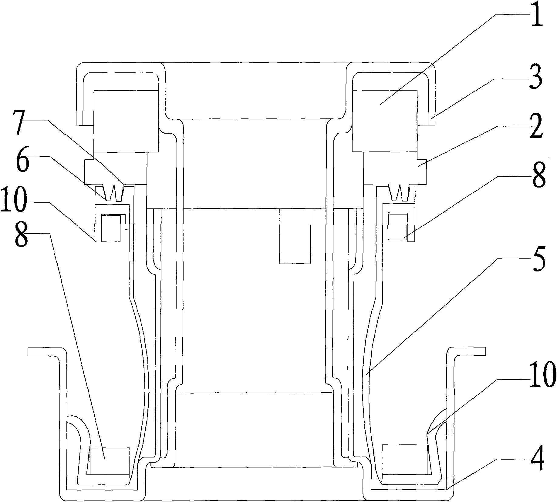
[0030] Such as figure 1 , 6As shown in and 7, a seal assembly includes a moving ring body 1, a static ring body 2, a moving ring shaft sleeve seat 3, a static ring shaft sleeve seat 4, a rubber sealing sleeve 5, and two sets of fixed skeletons 10, rubber The upper surface of the sealing sleeve 5 cooperates with the lower surface of the static ring body 2, the lower end of the rubber sealing sleeve 5 is set in the sleeve seat 4 of the static ring, the lower surface of the moving ring body 1 cooperates with the upper surface of the static ring body 2, and the rubber seal The upper surface of the sleeve 5 cooperates with the lower surface of the static ring body 2 in the manner of a tapered convex body 6 and a tapered groove 7 . The tapered convex body 6 is arranged on the lower surface of the stationary ring body 2, and the corresponding tapered groove 7 is arranged on the upper surface of the rubber sealing sleeve 5. The tapered convex body 6 and the corresponding tapered conc...

Embodiment 2

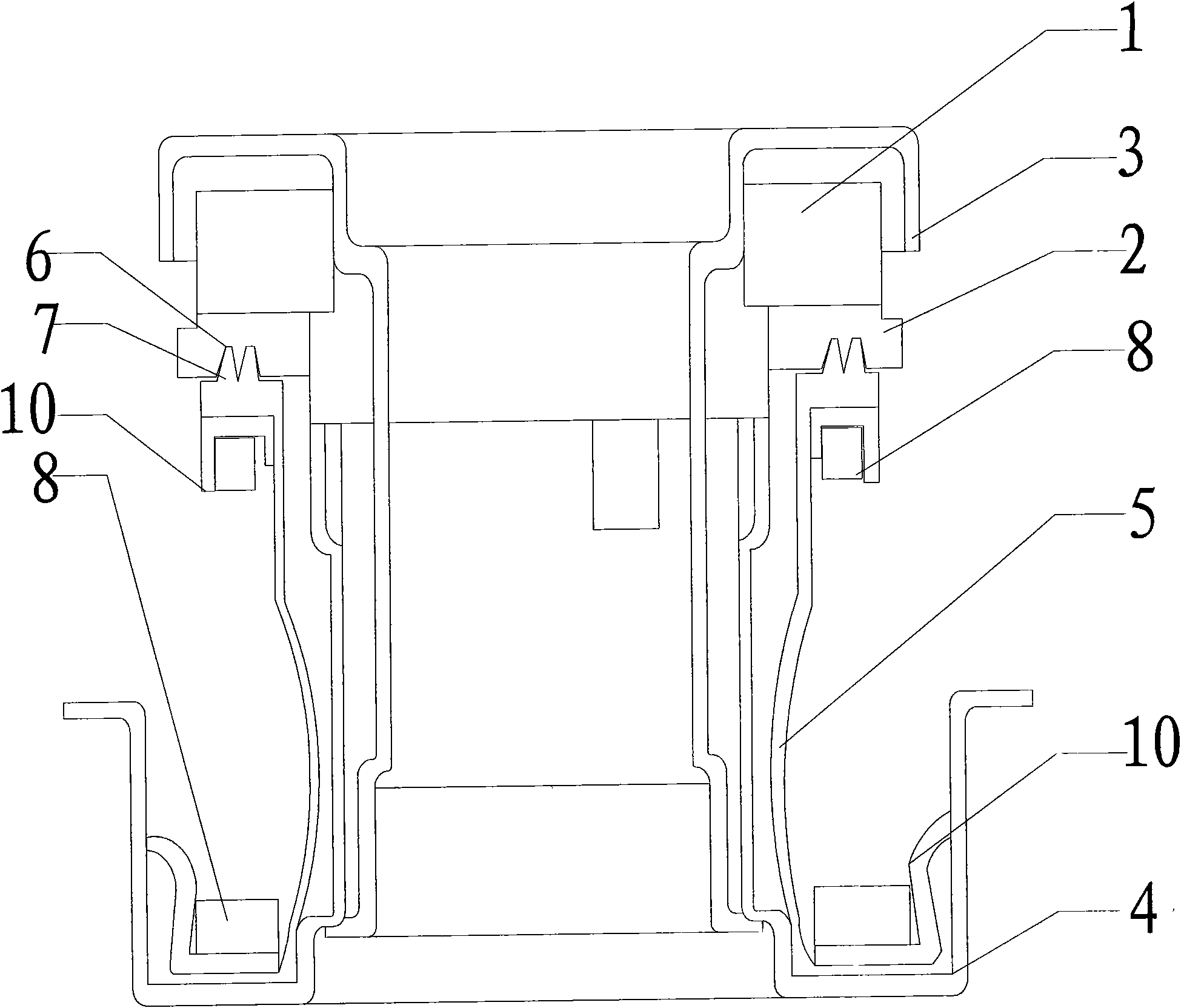
[0032] Such as figure 2 , 6 As shown in and 7, a seal assembly includes a moving ring body 1, a static ring body 2, a moving ring shaft sleeve seat 3, a static ring shaft sleeve seat 4, a rubber sealing sleeve 5, and two sets of fixed skeletons 10, rubber The upper surface of the sealing sleeve 5 cooperates with the lower surface of the static ring body 2, the lower end of the rubber sealing sleeve 5 is set in the sleeve seat 4 of the static ring, the lower surface of the moving ring body 1 cooperates with the upper surface of the static ring body 2, and the rubber seal The upper surface of the sleeve 5 cooperates with the lower surface of the static ring body 2 in the manner of a tapered convex body 6 and a tapered groove 7 . The tapered convex body 6 is arranged on the upper surface of the rubber sealing sleeve 5, and the corresponding tapered groove 7 is arranged on the lower surface of the static ring body 2. The tapered convex body 6 and the corresponding tapered The s...

Embodiment 3

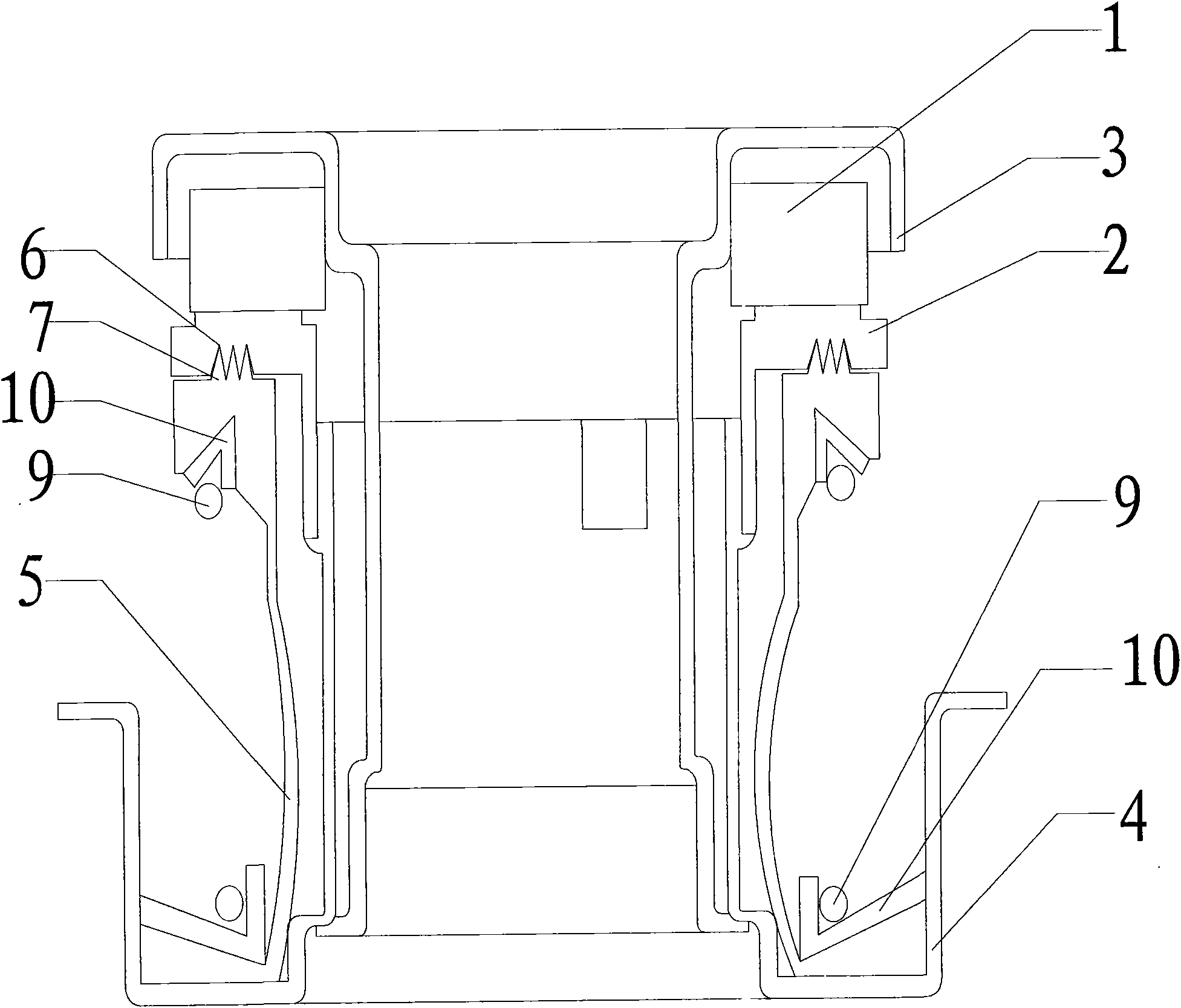
[0034] Such as image 3 , 6 As shown in and 7, a seal assembly includes a moving ring body 1, a static ring body 2, a moving ring shaft sleeve seat 3, a static ring shaft sleeve seat 4, a rubber sealing sleeve 5, and two sets of fixed skeletons 10, rubber The upper surface of the sealing sleeve 5 cooperates with the lower surface of the static ring body 2, the lower end of the rubber sealing sleeve 5 is set in the sleeve seat 4 of the static ring, the lower surface of the moving ring body 1 cooperates with the upper surface of the static ring body 2, and the rubber seal The upper surface of the sleeve 5 cooperates with the lower surface of the static ring body 2 in the form of a tapered convex body 6 and a tapered groove 7. The tapered convex body 6 is arranged on the upper surface of the rubber sealing sleeve 5, corresponding to the tapered The groove 7 is arranged on the lower surface of the static ring body 2, the shape of the tapered convex body 6 and the corresponding ta...


PUM


Abstract

The invention discloses a sealing part assembly which comprises a movable ring body, a stationary ring body, a movable ring shaft sleeve base, a stationary ring shaft sleeve base, a rubber sealing sleeve and two groups of fixed frameworks. The upper surface of the rubber sealing sleeve is matched with the lower surface of the static ring body; the lower end part of the rubber sealing sleeve is sleeved in the stationary ring shaft sleeve base; and the lower surface of the movable ring body is matched with the upper surface f the stationary ring body. The sealing part assembly is characterized in that the upper surface of the rubber sealing sleeve and the lower surface of the stationary ring body are matched in a manner of a convex body with a taper and a groove with a taper; and springs or magnets are sleeved on the fixed frameworks at the upper end and the lower end on the outer surface of the rubber sealing sleeve. The invention has the advantages of simple manufacturing process, strong university, reliable sealing performance and long service life.

Description

technical field [0001] The invention relates to a seal assembly structure, in particular to a water pump seal assembly structure used in the automotive field. Background technique [0002] At present, the connection between the rubber seal sleeve and the static ring body used in the structure of the automobile water pump seal in China, the domestic seal assembly still uses the glue bonding technology, which has low production efficiency and poor manufacturability. The phenomenon of manual work is serious, and it is limited to the nature of the glue to be bonded. In actual use, it is easily affected by environmental conditions. Glue aging, degumming, and peeling occur at the joint of the glue layer. The long-term sealing cycle is uncertain, and it is difficult to be suitable for automation. Process requirements for high-efficiency production on the assembly line. Although the utility model patent ZL 200620126131.5 announced by the applicant on November 28, 2007 proposed a no...

Claims


Application Information

Patent Timeline
Patent Type & Authority Applications(China)
IPC IPC(8): F16J15/16F04D29/16
Inventor 江雪忠
Owner 江雪忠
Why Eureka
Try Eureka