Flow sensor of heat energy meter

A technology of flow sensor and calorimeter, which is applied in the direction of calorimeter, measuring heat, measuring flow/mass flow, etc. It can solve the problems of large pressure loss of hot water, few common parts, easy wear of friction parts, etc., and achieve hot water pressure Small loss, wide flow range ratio, and good flow capacity

Inactive Publication Date: 2010-01-06
周文庆
View PDF0 Cites 3 Cited by
  • Summary
  • Abstract
  • Description
  • Claims
  • Application Information

AI Technical Summary

Problems solved by technology

Due to the existence of the shaft and bearing sleeve of the rotary impeller of the water meter structure: the friction parts are easy to wear, the movement parts are easy to accumulate scale, and it is difficult to remove scale, resulting in changes in the measurement performance of the heat meter, short service life, and loss of hot water pressure in the water meter structure. Large, poor flow capacity
The structural form of the water meter has the disadvantages of many parts, few common parts, large appearance and high cost; the structural type of the water meter uses magnetic components to indicate the flow rate, has no magnetic shielding, and is easily disturbed by external strong magnetic fields.

Method used


Image

  • Flow sensor of heat energy meter
  • Flow sensor of heat energy meter

Examples


Embodiment Construction

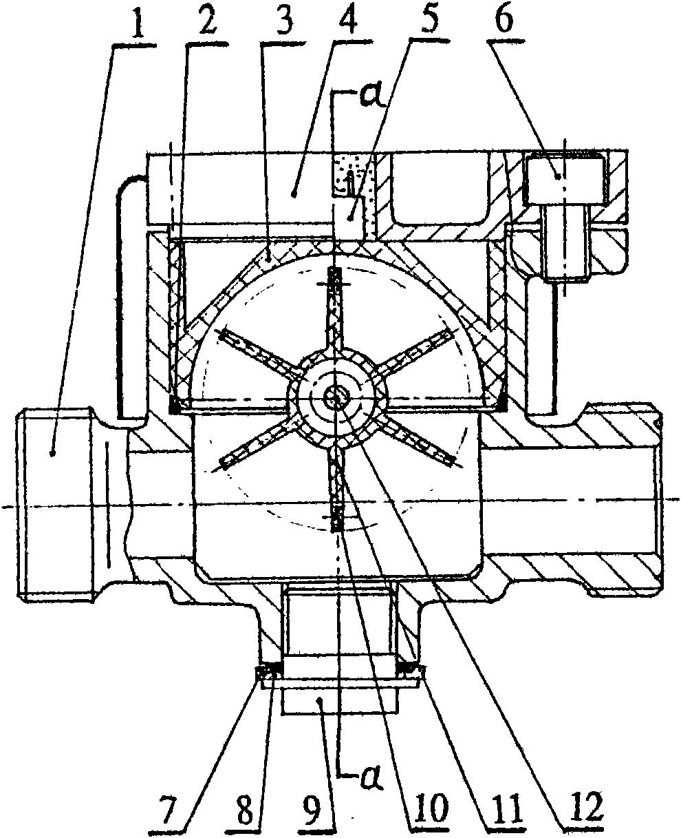
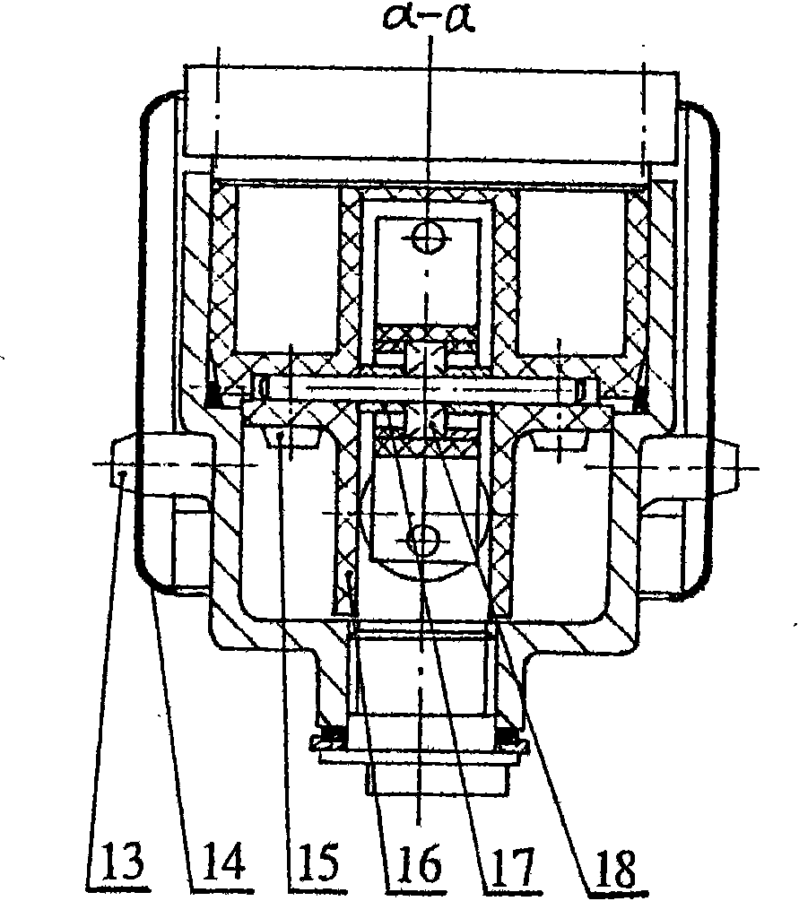
[0010] The thermal energy meter flow sensor of the present invention is realized in this way, which will be described in detail below in conjunction with the accompanying drawings. See figure 1 , figure 2 The thermal energy meter flow sensor is composed of: shell 1, sealing ring 2, impeller seat 3, gland 4, magnetoelectric converter 5, screw 6, washer 7, gasket 8, plug 9, magnetic element 10, impeller 11 , shaft 12, screw 13, magnetic shield 14, screw 15, rectifying plate 16, sleeve 17, rolling bearing 18, characterized in that: rolling bearing 18 is fixed in the hole of impeller 11 and the middle part of shaft 12 to form the impeller assembly; 2 sleeves 17 is installed on both sides of the shaft 12 and the rolling bearing 18 of the impeller assembly, the impeller assembly is placed in the groove of the impeller seat 3, and the shaft 12 of the impeller assembly is compressed with two rectifying plates 16 and screws 15 to form a movement. Put the sealing ring 2 into the hole...


PUM


Abstract

The invention relates to a flow sensor of a heat energy meter, which is characterized in that a rolling bearing is fixed in an impeller hole to form an impeller component together with the middle part of a shaft; two sleeves are arranged on two sides of the shaft of the impeller component and the rolling bearing, the impeller component is arranged in a groove of an impeller seat, and two eddy plates and bolts compact the shaft of the impeller component to form a machine core; a sealing ring and the machine core are arranged in a shell hole, and the machine core is compacted by a gland bush and bolts; and a magneto-electric converter is arranged in an upper hole of the gland bush, a magnetic shield is fixed outside the shell by using bolts, and the bottom of the shell is provided with a sewage outlet. By using the flow sensor of the heat energy meter, the hot water stream acts on an impeller vane in the tangential direction, the impeller generates revolution to perform flow measurement, and a permanent magnet material magnetic element is used for indicating the flow, the magnetic shield and the sewage outlet are arranged outside the shell, and the hot water flows through the shell directly, thus the low sensor of the heat energy meter has the characteristics of long service life, convenient pollution discharge, reliable performance, small hot water pressure loss, good flow capacity, wide flow range ratio, small appearance volume, low manufacturing cost and the like.

Description

technical field [0001] The invention relates to a thermal energy meter flow sensor. Background technique [0002] At present, in the field of thermal energy meter flow sensor technology at home and abroad, the traditional water meter structure is used to measure the flow of hot water. Due to the existence of the shaft and bearing sleeve of the rotary impeller of the water meter structure: the friction parts are easy to wear, the movement parts are easy to accumulate scale, and it is difficult to remove scale, resulting in changes in the measurement performance of the heat meter, short service life, and loss of hot water pressure in the water meter structure. Large, poor circulation. The structural form of the water meter has the disadvantages of many parts, few common parts, large size, and high cost; the structural type of the water meter uses magnetic components to indicate the flow rate, has no magnetic shielding, and is easily disturbed by external strong magnetic field...

Claims


Application Information

Patent Timeline
Patent Type & Authority Applications(China)
IPC IPC(8): G01F1/06G01F1/075G01K17/00
Inventor 周文庆
Owner 周文庆
Why Eureka
Try Eureka