Track car drive system, and track car using the system

A technology for rail vehicles and drive systems, which is used in engine-driven traction, railway vehicles, vehicle components, etc. to reduce vibration, improve ride feel, and reduce noise.

Active Publication Date: 2010-01-06
HITACHI NICO TRANSMISSION
View PDF2 Cites 13 Cited by
  • Summary
  • Abstract
  • Description
  • Claims
  • Application Information

AI Technical Summary

Problems solved by technology

In this proposal, a fixed brake or fixed clutch structure is included on one

Method used


Image

  • Track car drive system, and track car using the system
  • Track car drive system, and track car using the system
  • Track car drive system, and track car using the system

Examples


Embodiment Construction

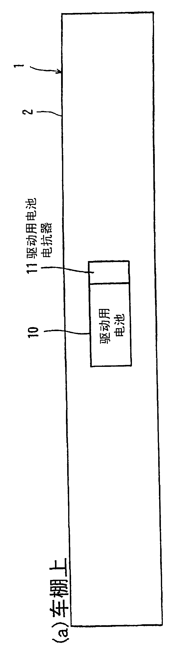
[0035] Figure 1A and Figure 1B It is a schematic diagram showing an example of a rail vehicle to which the rail vehicle drive system of the present invention is applied, especially a rail vehicle, Figure 1A is the top view on the carport, Figure 1B It is the figure which looked at the bottom with the plane along the bottom under the floor. Such as Figure 1A As shown, a driving battery 10 and a driving battery reactor 11 are installed on the carport 2 of the rail vehicle 1 .

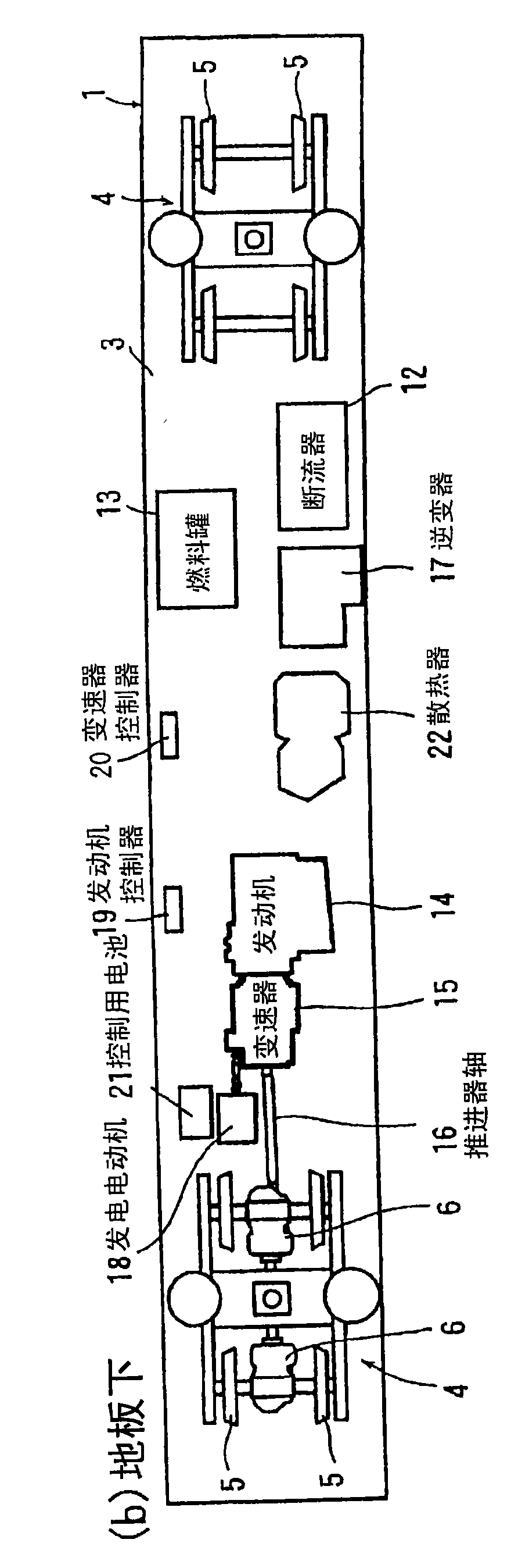
[0036] Such as Figure 1B Shown, configuration is equipped with and supports rail vehicle 1, and the chassis 4,4 that can travel on track (line) wheel 5 and speed reducer 6, under the floor 3 of rail vehicle 1, be provided with the following all in the mode of suspension: Various devices are disclosed. That is, a fuel tank 13 that stores fuel such as gasoline and is formed as a supply source, an engine 14 composed of an internal combustion engine such as a diesel engine driven by receiving fuel fr...


PUM


Abstract

Provided is a track car drive system, which is assisted by a generator motor so that it may attain a gear array for equalizing the gear numbers and the gear ratios at the individual gears as a transmission for the forward speed and the backward speed and which can be combined with the generator motor. A transmission (15) for receiving the output of an engine (14) at an input shaft (30) is constituted by combining a forward gear train (31) and a backward gear train (32) with two intermediate shafts (41 and 42) having different speed change gear stages (51 to 54) between themselves and an output shaft (45). By shifting/fastening a first clutch (43) or a second clutch (44) selectively, the rotation of either the forward gear train (31) or the backward gear train (32) is transmitted to either of the intermediate shafts (41 and 42). When one of the speed change gear stages (51 to 54) is selected, the same gear number and gear ratio are taken no matter whether the track car might run forward or backward. The assist force by the generator motor (18) is applied from a differential mechanism (55) through the two intermediate shafts (41 and 42) to the output shaft (45).

Description

technical field [0001] The present invention relates to a drive system for rail vehicles provided with a transmission for shifting and outputting rotational output of an engine, and to a rail vehicle using the same. Background technique [0002] Conventional drive systems for internal combustion locomotives are configured to input the output of an engine such as a diesel engine to a transmission (transmission device) and transmit the output of the transmission to wheels via a drive shaft. In this system, the speed change is carried out through the transmission. On the other hand, as another type of drive system, a system has been proposed in which all the output of the engine is input to the generator, the electric energy output from the generator is input to the inverter, the frequency is converted, and the system equipped on the chassis is electrically driven. motor. Even when the engine is stopped, the electric power from the battery can be used to run the motor. In th...

Claims


Application Information

Patent Timeline
IPC IPC(8): B60K6/365B60K6/26B60K6/40B60K6/48B60K6/547B60K17/04B60L11/14B60W10/08B60W10/10B60W20/00B61C7/04B61C9/12F16H3/14F16H61/02F16H63/40F16H59/74F16H61/688B60K6/36B60K6/485B60L50/16B61C3/02B61C5/00F16H61/68F16H61/684
CPCY02T10/6286B60L2200/26F16H2200/0043B60W10/06B60K6/48B61C9/12B61C7/04F16H2200/2005F16H3/725B60W20/00B60K2006/4816Y02T30/16B60L2270/145Y02T10/6256B60L11/14Y02T10/7077F16H2037/049B60W10/08Y02T10/6221B60L50/16Y02T10/62Y02T30/00Y02T10/7072B60W10/02B60W20/50Y02T10/70
Inventor 柿沼博彦佐藤岩井原祯之稻场匡中村秀树柄泽亮小野贵博
Owner HITACHI NICO TRANSMISSION
Why Eureka
Try Eureka