
Liquid crystal display

A technology of liquid crystal display device and display part, which is applied in the direction of static indicators, instruments, etc., and can solve the problems such as the reduction of specific sense, and achieve the effect of improving contrast sense and suppressing the change of color sense

Inactive Publication Date: 2010-01-06
SHARP KK
View PDF1 Cites 10 Cited by
  • Summary
  • Abstract
  • Description
  • Claims
  • Application Information

AI Technical Summary

Problems solved by technology

In this way, in liquid crystal display devices, since the peak luminance is maintained at a constant value, the sense of contrast decreases compared with CRT.

Method used


Image

  • Liquid crystal display
  • Liquid crystal display
  • Liquid crystal display

Examples


no. 1 approach

[0095]

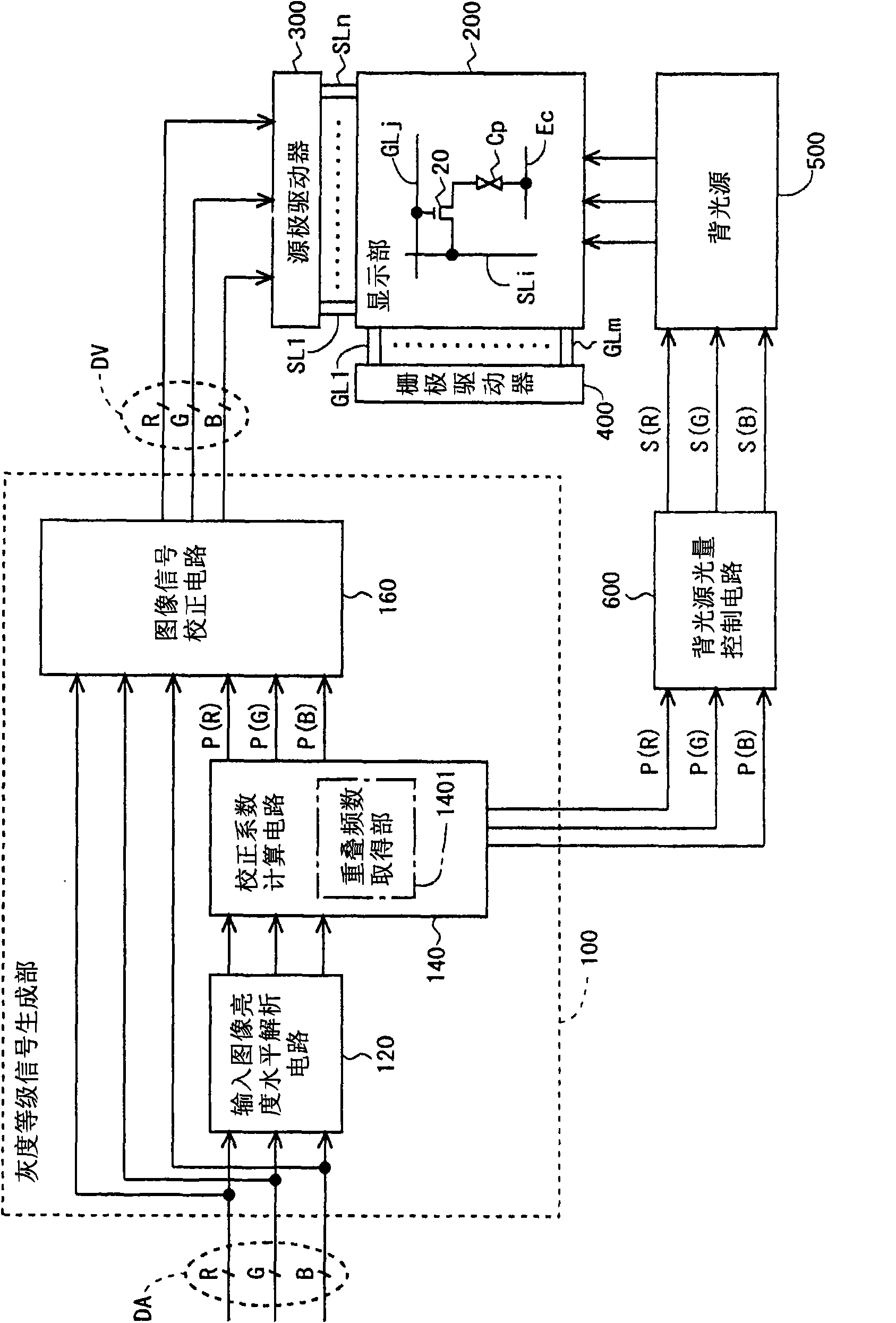
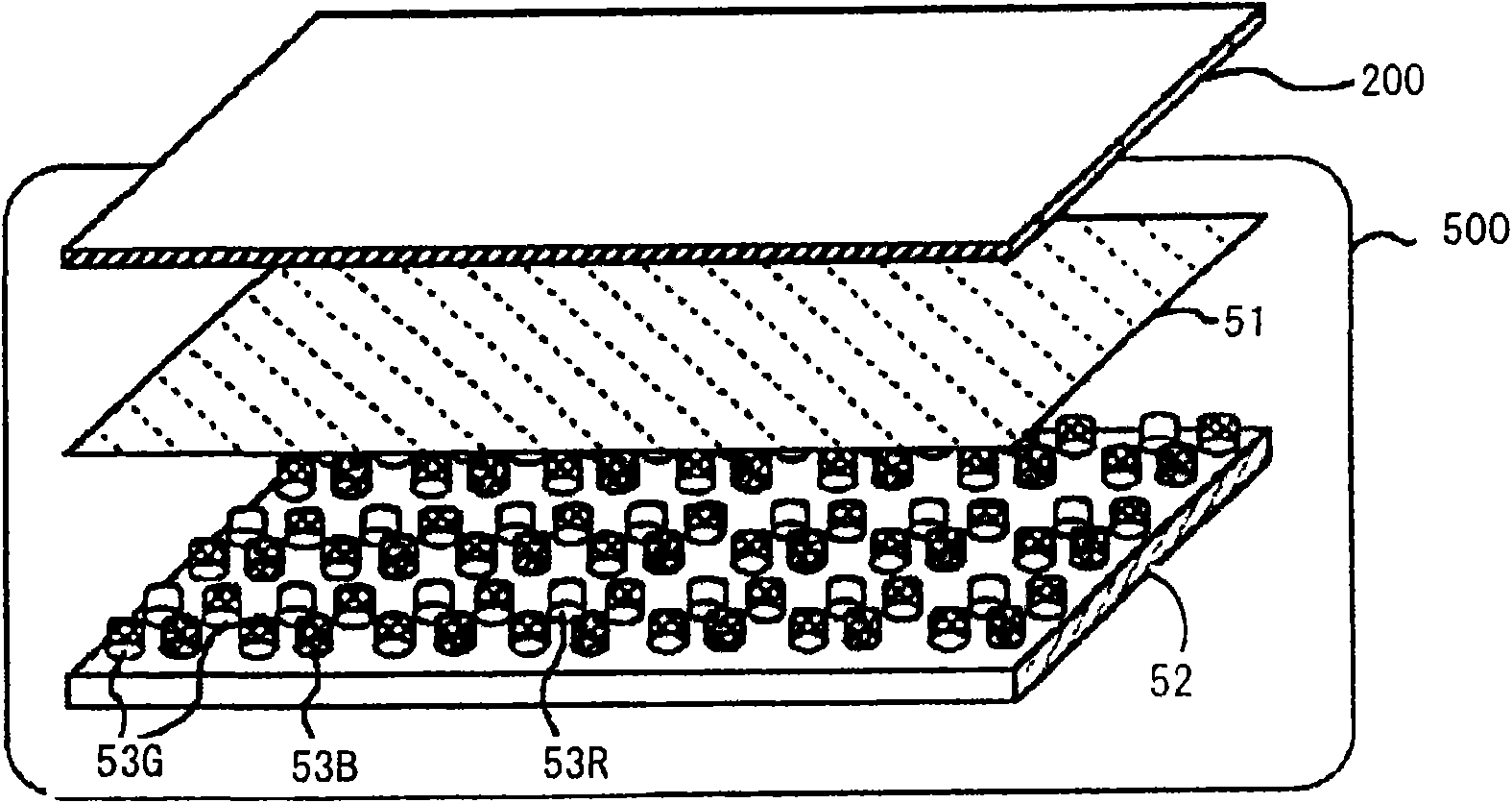
[0096] figure 1 It is a block diagram showing the overall configuration of the liquid crystal display device according to the first embodiment of the present invention. This liquid crystal display device includes: a gradation signal generating unit 100, a display unit (liquid crystal display panel) 200, a source driver (video signal line driving circuit) 300, a gate driver (scanning signal line driving circuit) 400, and a backlight 500. , and a backlight light quantity control circuit (luminous intensity adjustment unit) 600.

[0097] The gradation signal generation unit 100 receives the digital image signal DA (RGB image signal) from the outside, and uses the frequency distribution (hereinafter referred to as "brightness level distribution") of the luminance level (brightness value) of one frame of data of each RGB color , and output the grayscale signal DV representing the grayscale value of the data of each color of RGB, and the correction coefficients P(R), P(...

no. 2 approach

[0146]

[0147] Figure 13 It is a block diagram showing the overall configuration of a liquid crystal display device according to a second embodiment of the present invention. In the present embodiment, the configuration in the gradation signal generating unit 100 is different from that of the above-mentioned first embodiment, so it will be described below.

[0148] Unlike the first embodiment described above, in this embodiment, the input image luminance level analysis circuit 120 includes a most frequent luminance level acquisition unit 1201 . In addition, the overlap frequency acquisition unit is not included in the correction coefficient calculation circuit 140 . The most frequent luminance level acquisition unit 1201 acquires the luminance level with the largest number of pixels (hereinafter referred to as "the most frequent luminance level") for the data of each RGB color based on the acquired luminance level distribution similarly to the first embodiment. The corre...


PUM


Abstract

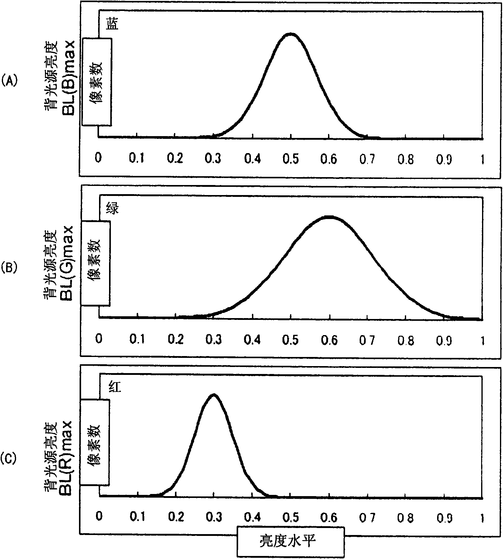
A liquid crystal display, specifically a transmission type liquid crystal display having a built-in backlight at the rear side of a panel. The liquid crystal display has a gradation signal generator section (100) including an input image luminance level analyzing circuit (120) for acquiring the luminance level distribution for each color based on the RGB image signals, a correction coefficient computing circuit (140) for calculating the correction coefficients based on the luminance level distribution for each color and an image signal correction circuit (160) for correcting the luminance levels of the RGB image signals based on the correction coefficients, and a backlight intensity control circuit (600) for adjusting the light-emitting amount of each color LED based on the correction coefficients. The correction coefficient computing circuit (140) calculates the correction coefficients such that correction of the luminance levels reduces the difference in the luminance level distribution among each of RGB colors. The backlight intensity control circuit (600) adjusts the light-emitting amount of each color to cancel variation in the luminance level and variation in the light-emitting amount.

Description

technical field [0001] The present invention relates to a liquid crystal display device, and more particularly to a transmissive liquid crystal display device including a backlight on the rear surface of a panel. Background technique [0002] Liquid crystal display devices have features such as thinness, low power consumption, and high definition. Due to the development of manufacturing technology in recent years, the size of the screen is advancing. Therefore, liquid crystal display devices are also being used in televisions that mainly use CRT (Cathode Ray Tube: Cathode Ray Tube) conventionally. However, the image displayed by the liquid crystal display device has a lower sense of contrast (difference in the brightness of the bright part and the dark part perceived by humans) compared with the image displayed by the CRT, and the difference due to the viewing angle (viewing angle) The problem of changing color perception. In addition, "the change in color sense" means tha...

Claims


Application Information

Patent Timeline
Patent Type & Authority Applications(China)
IPC IPC(8): G09G3/36G02F1/133G09G3/20G09G3/34
CPCG09G2360/16G09G2320/0242G09G3/3426G09G2320/0666G09G2320/0646G09G3/3648G09G2320/0271G09G3/3413
Inventor 增田岳志四宫时彦
Owner SHARP KK
Learn More