Laser cutting fed material and baiting conveyor

A laser cutting and conveyor technology, used in glass cutting devices, glass manufacturing equipment, electrical components, etc., can solve problems such as the inability of the scribing effect to meet the requirements for use, the wrong alignment of the battery plate, and the flawed scribing. To achieve the effect of shortening process production time, improving productivity and beautiful appearance

Active Publication Date: 2013-01-16
北京清大天达光电科技股份有限公司
View PDF0 Cites 0 Cited by
  • Summary
  • Abstract
  • Description
  • Claims
  • Application Information

AI Technical Summary

Problems solved by technology

In the past, the marking and loading and unloading machines for solar panels could only transfer a single piece of glass to enter the relative marking stage, and the process of the next unit must be waited until the marking of this stage is completed. If there is a problem during the period, For example, if there is a defect in the marking, the alignment of the battery board is wrong, and the marking effect cannot meet the requirements for use, then the entire production line will be in a relatively waiting state until the battery board has completely completed the operation of this process. normal operation
Leading to low output of products, decreased productivity, etc.

Method used


Image

  • Laser cutting fed material and baiting conveyor
  • Laser cutting fed material and baiting conveyor
  • Laser cutting fed material and baiting conveyor

Examples


Embodiment Construction

[0027] The following examples are used to illustrate the present invention, but are not intended to limit the scope of the present invention.

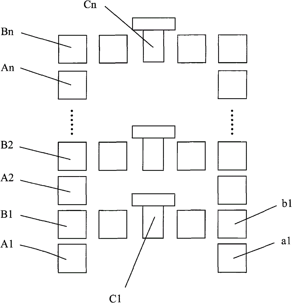
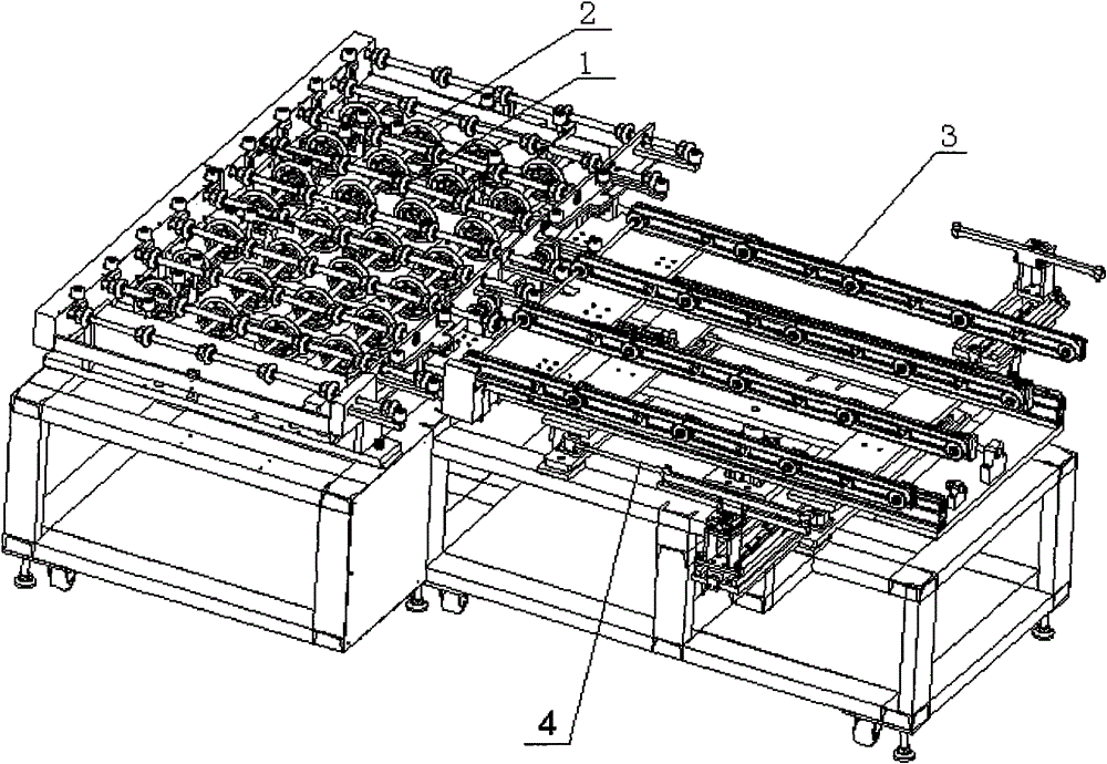
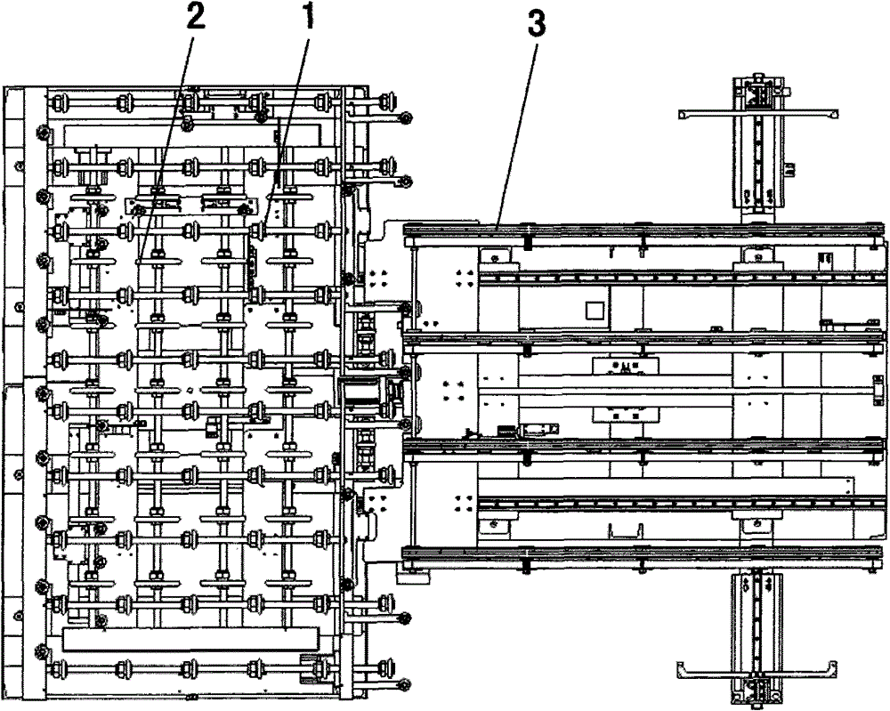
[0028] Such as figure 1 As shown, the laser cutting loading and unloading machine involved in the present invention includes n feeding machine transmission mechanisms, loading cross guide rollers, unloading machine transmission mechanisms, and unloading cross guide rollers. The conveying mechanism of the feeding machine is arranged on one side of the laser marking machine (C1~Cn in sequence), arranged in a straight line, A1~An in sequence. The feeding cross guide rollers and the feeding machine conveying mechanism are arranged alternately, B1~Bn in sequence. The conveying mechanism of the unloading machine (b1~bn in sequence) and the unloading cross guide roller are set on the other side of the laser marking machine, and the arrangement between the two is the same as the arrangement of the feeding conveying mechanism and the feeding c...


PUM


Abstract

The invention relates to a laser cutting fed material and baiting conveyor which comprises a plurality of feed machine conveying mechanisms, a plurality of fed material cross conveying roller ways, a plurality of baiting cross conveying roller ways and a plurality of baiting machine conveying mechanisms, wherein the feed machine conveying mechanisms are used for conveying solar panels to be engraved, and each feed machine conveying mechanism is provided with a sensor used for detecting whether a solar panel is on a laser engraving machine corresponding to the feed machine mechanism and engraved or not; the fed material cross conveying roller ways are arrayed at intervals with the feed machine conveying mechanisms and used for deciding whether to convey glass plates to be detected to the laser engraving machines or not according to detection signals of the sensors; the baiting cross conveying roller ways are used for conveying engraved solar panels to the baiting machine conveying mechanisms; and the baiting machine conveying mechanisms are arranged corresponding to the feed machine conveying mechanisms and used for the engraved solar panels to a next working procedure. The invention greatly shortens the time of a manufacturing process of the solar panels, simplifies, batches and rationalizes the manufacturing process of the solar panels and effectively improves the production efficiency of products.

Description

technical field [0001] The invention relates to the field of laser cutting, in particular to a loading and unloading conveyor for a laser cutter. Background technique [0002] Laser cutting loading and unloading machine is used in the scoring stage of solar panel production. Due to the different process sequences of solar cells, it is generally divided into two transmission methods: flat delivery of infrared laser marking panels and green laser marking. Flip way. In the past, the marking and loading and unloading machines for solar panels could only transfer a single piece of glass to enter the relative marking stage, and the process of the next unit must be waited until the marking of this stage is completed. If there is a problem during the period, For example, if there is a defect in the marking, the alignment of the battery board is wrong, and the marking effect cannot meet the requirements for use, then the entire production line will be in a relatively waiting state u...

Claims


Application Information

Patent Timeline
Patent Type & Authority Patents(China)
IPC IPC(8): C03B35/00C03B33/09H01L31/18
CPCY02P40/57Y02P70/50
Inventor 文亦武刘杰薛亮宋展鹏
Owner 北京清大天达光电科技股份有限公司
Why Eureka
Try Eureka