Micropower power supply converting circuit
A power conversion and micro-power technology, which is applied in the output power conversion device, the conversion of DC power input to DC power output, and the adjustment of electrical variables, etc. , large isolation capacitance, etc., to achieve the effect of ensuring reliability and stability, high mean time between failures, and high isolation voltage level
- Summary
- Abstract
- Description
- Claims
- Application Information
AI Technical Summary
Problems solved by technology
Method used
Image
Examples
Embodiment 1
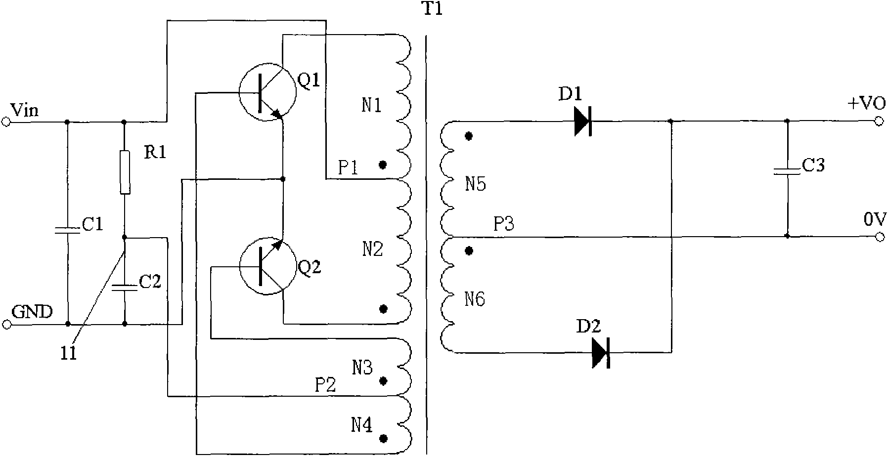
[0030] For the circuit diagram of Embodiment 1 of the micropower power conversion circuit, see figure 2 As shown, it includes a first resistance circuit, a first capacitance circuit, a second capacitance circuit, a first switching transistor Q1, a second switching transistor Q2, a transformer T1, a first diode D1, a second diode D2, a first Two resistor circuits, a third capacitor circuit, wherein figure 2 The first resistor circuit includes the first resistor R1, but the embodiment of the present invention does not limit the first resistor circuit to only include the first resistor, and multiple resistors can also be combined to achieve the same function as the first resistor; figure 2 The first capacitor circuit includes the first capacitor C1, the second capacitor circuit includes the second capacitor C2, and the third capacitor circuit includes the third capacitor C3; however, the embodiment of the present invention does not limit the first capacitor circuit to only inc...
Embodiment 2
[0051] Such as Figure 5 Shown, in order to further improve the present invention, in figure 2 On the basis of the illustrated embodiment, the micropower power conversion circuit adds a second resistor circuit, and the second resistor circuit includes a second resistor R2; however, the embodiment of the present invention does not limit the second resistor circuit to only include a second resistor , the same function as the second resistor can also be realized by a plurality of resistors through circuit combination. One end of the second resistor circuit is connected to the first connection line 11, and the other end of the second resistor circuit is connected to the second tap P2. Reduce the base drive voltage of the switching transistor, suppress the switching transistor from entering deep saturation, and improve the start-up performance of the circuit; when the two switching transistors change state, the second resistor R2 absorbs the sharp energy generated at the moment o...
Embodiment 3
[0053] Such as Figure 6 Shown, in order to further improve the present invention, in figure 2 On the basis of the illustrated embodiment, the micropower power conversion circuit adds a third resistor circuit, and the third resistor circuit includes a third resistor R3; however, the embodiment of the present invention does not limit that the third resistor circuit can only include a third resistor , the same function as the third resistor can also be realized by a plurality of resistors through circuit combination. The third resistance circuit is connected in parallel at both ends of the output terminal, mainly to suppress the increase of the output voltage of the product due to load changes when the product is no-load, and improve the output characteristics of the product under light-load and no-load conditions.
PUM
 Abstract
Description
Claims
Application Information
 - R&D
- Intellectual Property
- Life Sciences
- Materials
- Tech Scout
- Unparalleled Data Quality
- Higher Quality Content
- 60% Fewer Hallucinations
Browse by: Latest US Patents, China's latest patents, Technical Efficacy Thesaurus, Application Domain, Technology Topic, Popular Technical Reports.
© 2025 PatSnap. All rights reserved.Legal|Privacy policy|Modern Slavery Act Transparency Statement|Sitemap|About US| Contact US: help@patsnap.com


