Micropower power supply converting circuit

A power conversion and micro-power technology, which is applied in the output power conversion device, the conversion of DC power input to DC power output, and the adjustment of electrical variables, etc. , large isolation capacitance, etc., to achieve the effect of ensuring reliability and stability, high mean time between failures, and high isolation voltage level

Inactive Publication Date: 2012-02-29
MORNSUN GUANGZHOU SCI & TECH
View PDF4 Cites 0 Cited by
  • Summary
  • Abstract
  • Description
  • Claims
  • Application Information

AI Technical Summary

Problems solved by technology

[0003] Therefore, there are generally several disadvantages: 1. Current peaks will be generated at the moment of switching transition; 2. Due to the small number of components, the circuit has no protection function, and the switching power device is easily damaged; 3. Since the primary and secondary sides of the transformer are wound together, the The isolation between the input and output terminals of the circuit is not easy to improve, and the isolation capacitance is large; 4. Due to the high coupling coefficient of the transformer, when a short circuit occurs at the output terminal, the switch tube is easily broken down, making the power converter easily damaged

Method used


Image

  • Micropower power supply converting circuit
  • Micropower power supply converting circuit
  • Micropower power supply converting circuit

Examples


Embodiment 1

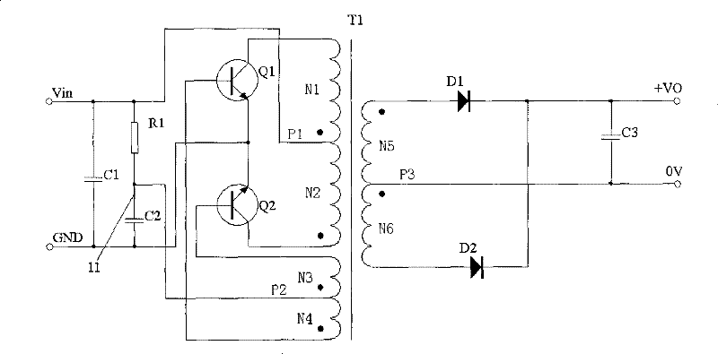
[0030] For the circuit diagram of the first embodiment of the micropower power conversion circuit, see figure 2 As shown, it includes a first resistance circuit, a first capacitor circuit, a second capacitor circuit, a first switching transistor Q1, a second switching transistor Q2, a transformer T1, a first diode D1, a second diode D2, and a second diode. The second resistance circuit, the third capacitor circuit, where figure 2 The first resistance circuit in the middle includes the first resistance R1, but the embodiment of the present invention does not limit the first resistance circuit to only include the first resistance, and multiple resistances can also be combined with circuits to achieve the same function as the first resistance; figure 2 The first capacitor circuit includes a first capacitor C1, the second capacitor circuit includes a second capacitor C2, and the third capacitor circuit includes a third capacitor C3; however, the embodiment of the present invention ...

Embodiment 2

[0051] Such as Figure 5 As shown, in order to further improve the present invention, figure 2 On the basis of the illustrated embodiment, the micro-power power conversion circuit adds a second resistor circuit, and the second resistor circuit includes a second resistor R2; however, the embodiment of the present invention does not limit the second resistor circuit to only include the second resistor. It is also possible to combine multiple resistors to achieve the same function as the second resistor. One end of the second resistance circuit is connected to the first connection line 11, and the other end of the second resistance circuit is connected to the second tap P2. The working principle is that at the moment of starting, the second resistance R2 absorbs the energy of the third winding N3 and the fourth winding N4 to Reduce the base driving voltage of the switching transistor, prevent the switching transistor from entering deep saturation, and improve the starting performa...

Embodiment 3

[0053] Such as Image 6 As shown, in order to further improve the present invention, figure 2 On the basis of the illustrated embodiment, the micropower power conversion circuit adds a third resistor circuit, and the third resistor circuit includes a third resistor R3; however, the embodiment of the present invention does not limit the third resistor circuit to only include a third resistor. It is also possible to combine multiple resistors to achieve the same function as the third resistor. The third resistance circuit is connected in parallel at both ends of the output terminal, mainly to prevent the output voltage of the product from increasing due to load changes when the product is no-load, and to improve the output characteristics of the product under light load and no-load conditions.


PUM


Abstract

The invention discloses a micropower power supply converting circuit, which comprises a first resistive circuit, a first switching triode, a second switching triode, a transformer, a first diode, a second diode and a third capacitive circuit, wherein one end of a first resistor is connected with an input voltage end, while the other end is a first connecting wire; a variant-name end of a third winding is connected with the base of the second switching triode; and the other components are connected according to a common DC-DC conversion circuit. The micropower power supply converting circuit further comprises a second capacitive circuit and a fourth winding of the transformer, wherein one end of the second capacitive circuit is connected with the first connecting wire, while the other end is grounded; a variant-name end of the fourth winding is connected with a same-name end of the third winding to form a second tap of the transformer; and a same-name end of the fourth winding is connected with the base of the first switching triode and the second tap is connected with the first connecting wire. The micropower power supply converting circuit realizes DC-DC conversion with high isolation of input and an outputs and short circuit protection function on the application occasions of less than or equal to output power of 5W.

Description

Technical field [0001] The invention relates to a power conversion circuit, in particular to a micro-power direct current-direct current (DC-DC) conversion circuit. Background technique [0002] At present, the Royer topology is commonly used in micro-power DC-DC conversion, and the commonly used micro-power DC-DC conversion application circuits are such as figure 1 As shown, it includes a first resistance circuit R, a first switching transistor Q1, a second switching transistor Q2, a transformer T1, a first diode D1, a second diode D2, and a third capacitor circuit C3. The transformer includes a first winding N1, the second winding N2, the third winding N3, the fifth winding N5, the sixth winding N6, the first tap P1, the third tap P3, the first tap has the same name from the first winding N1 of the transformer and the second winding N2. The third tap is composed of the synonymous end of the fifth winding N5 of the transformer and the same end of the sixth winding N6; the first ...

Claims


Application Information

Patent Timeline
Patent Type & Authority Patents(China)
IPC IPC(8): H02M3/335H02M1/14H02M1/32
Inventor 尹向阳
Owner MORNSUN GUANGZHOU SCI & TECH
Why Eureka
Try Eureka