Isolated upper bridge bootstrap charge pump circuit for bridge driver and control method

A driver and isolation technology, applied in the field of semiconductor hybrid integrated circuits, can solve the problems of unsupplemented electric charge, application limitation, complex circuit structure, etc., and achieve the effects of improving assembly efficiency, strong scalability, and high isolation voltage.

Active Publication Date: 2019-06-21
XIAN MICROELECTRONICS TECH INST
View PDF5 Cites 0 Cited by
  • Summary
  • Abstract
  • Description
  • Claims
  • Application Information

AI Technical Summary

Problems solved by technology

However, the disadvantage of this circuit structure is that it is necessary to ensure that the capacitor C1 has sufficient charge. When the low-frequency continuous drive or the motor starts with a large duty cycle, the charge in the capacitor C1 cannot be replenished, and eventually the upper bridge power transistor Q1 cannot be turned on reliably.
Yan Yan, Li Fengfei and Wu Guojun published "Research on IR2110 Full-Bridge Drive Circuit Based on Charge Pump" on pages 49-52 of the 11th issue of "Mechanics and Electronics" in 2009, and proposed a timer 555-based upper bridge self-driving circuit. Take the charge pump circuit, but the structure of the circuit is complicated, and the isolation drive of the front and rear stages cannot be realized. When the power is large and the front and rear stages are isolated or the assembly density is high, its application is limited.

Method used


Image

  • Isolated upper bridge bootstrap charge pump circuit for bridge driver and control method
  • Isolated upper bridge bootstrap charge pump circuit for bridge driver and control method
  • Isolated upper bridge bootstrap charge pump circuit for bridge driver and control method

Examples


Embodiment Construction

[0034] The present invention will be further described in detail below in conjunction with specific embodiments, which are explanations of the present invention rather than limitations.

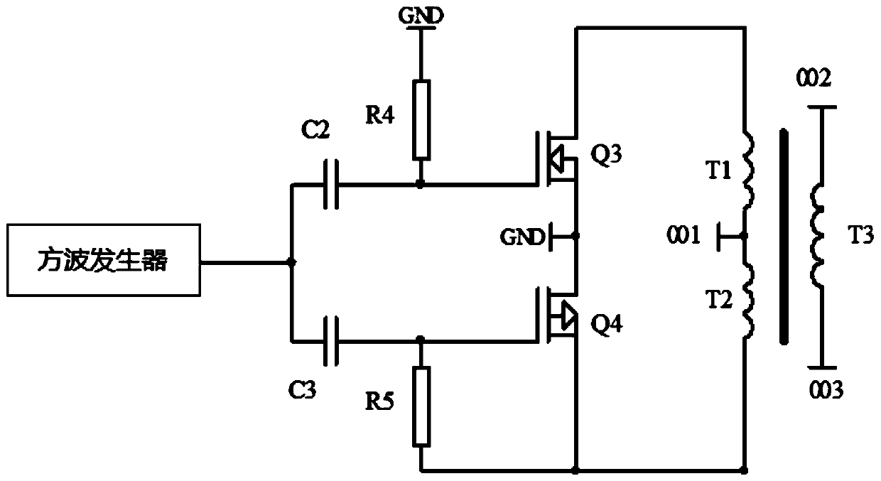
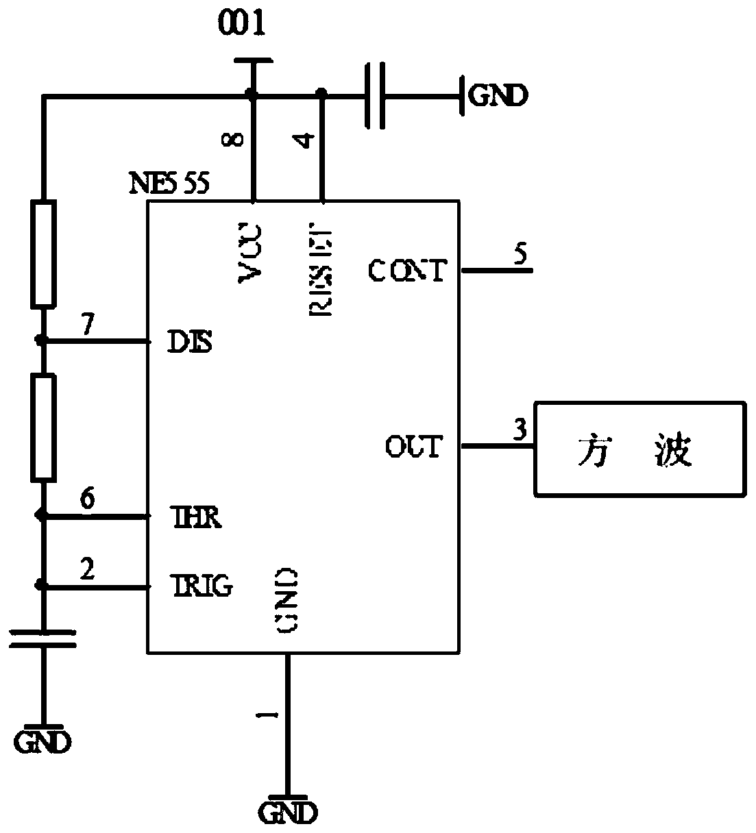
[0035] The invention relates to an isolated upper bridge bootstrap charge pump circuit for a bridge driver, comprising a square wave generator, two sets of pulse conversion circuits, a switch circuit and a transformer output circuit.

[0036] Among them, the square wave generator generates a square wave with a certain frequency and duty cycle, and connects capacitors C2 and C3 in parallel, the other end of capacitor C2 is connected in parallel with resistor R4 and the gate of N-type VDMOS Q3, and the other end of resistor R4 is grounded; The other end of the capacitor C3 is connected in parallel with the resistor R5 and the gate of the P-type VDMOS Q4, the other end of the resistor R5 is connected in parallel with the source of the P-type VDMOS Q4 and one end of the primary winding T2 of the t...


PUM


Abstract

The invention discloses an isolated upper bridge bootstrap charge pump circuit for a bridge driver and a control method. The isolated upper bridge bootstrap charge pump circuit for a bridge driver hasthe advantages of simple circuit structure, convenience in assembly and strong expandability. The circuit comprises a square wave generator, two groups of pulse conversion circuits, a switching circuit and a transformer output circuit, and the square wave generator, two groups of pulse conversion circuits, the switching circuit and the transformer output circuit are connected step by step; the square wave generator is used for generating square waves with the high level of VH and the low level of 0; the two groups of pulse conversion circuits are connected in parallel between the square wavegenerator and the switching circuit and are used for converting the square wave into positive and negative alternating pulse voltage signals and inputting the positive and negative alternating pulse voltage signals into the switching circuit; the transformer output circuit comprises a primary winding T1, a primary winding T2 and a secondary winding T3; the primary winding T1 and the primary winding T2 are connected end to end in a duplex winding mode to serve as input ends to be connected with the switching circuit, and a common end is connected with the input port 001 of the voltage source; and the secondary winding T3 adopts a single winding mode to serve as an output end, and two ends of the secondary winding T3 are respectively a voltage output positive port 002 and a voltage output negative port 003.

Description

technical field [0001] The invention relates to the technical field of semiconductor hybrid integrated circuits, in particular to an isolated upper bridge bootstrap charge pump circuit for a bridge driver and a control method. Background technique [0002] The bridge driver is a widely used electronic product. At present, the bridge power amplifier mainly uses N-type VDMOS or IGBT as the power switch tube. It needs to provide enough gate-source voltage for the power switch tube to ensure its reliable turn-on. Especially when the upper bridge is turned on, the source potential of the upper transistor is close to the power supply voltage. Therefore, to ensure the reliable turn-on of the upper transistor, it is necessary to realize the level conversion of the gate of the upper transistor, that is, "bootstrap". [0003] figure 1 Shown is the existing upper bridge bootstrap drive circuit, Vcc is the working voltage of the subsequent signal stage, V+ is the power supply voltage, ...

Claims


Application Information

Patent Timeline
Patent Type & Authority Applications(China)
IPC IPC(8): H02M3/07
Inventor 贺继鹏杨晓萍王俊峰王云孔令红卫丽超
Owner XIAN MICROELECTRONICS TECH INST
Why Eureka
Try Eureka