Hydraulic system
A hydraulic system and hydraulic technology, applied in the field of control valves, can solve problems such as high shaft power
- Summary
- Abstract
- Description
- Claims
- Application Information
AI Technical Summary
Problems solved by technology
Method used
Image

Examples
Embodiment Construction
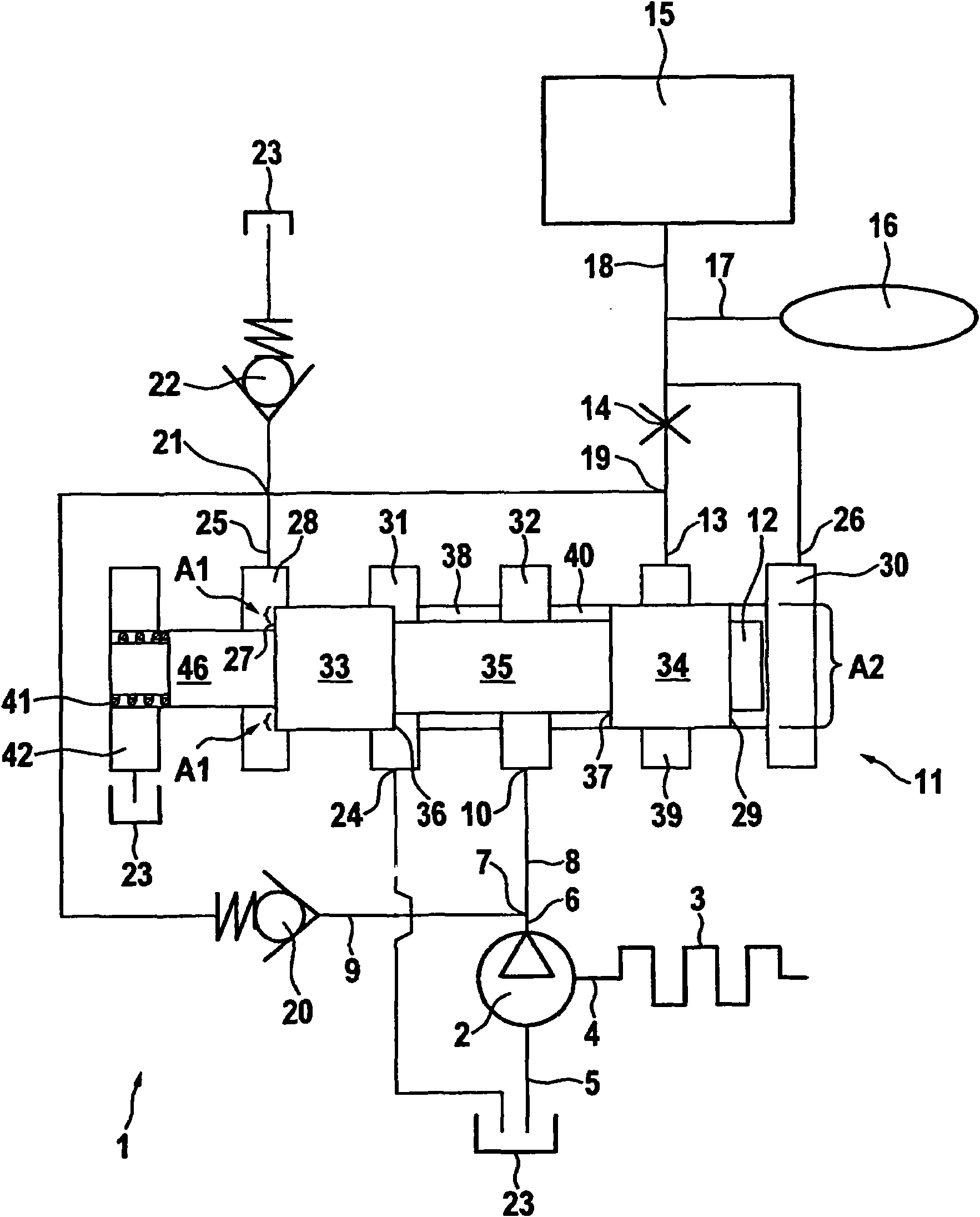
[0019] figure 1 A circuit diagram of an exemplary embodiment of a hydraulic system 1 according to the invention is shown. The hydraulic system includes a pump 2 which is driven by an internal combustion engine 3 . The drive takes place, for example, in that the drive shaft of the pump 2 is driven directly or indirectly via the crankshaft of the internal combustion engine 3 . The drive shaft 4 can be connected directly to the crankshaft, for example, but can also be driven via the crankshaft, for example via a gear transmission or a winding contact transmission. As soon as the internal combustion engine 3 is activated, the pump 2 is driven. The pump 2 comprises a suction side 5 and a pressure side 6 . The suction side 5 of the pump 2 is connected to an unpressurized storage tank 23 for hydraulic fluid. “Unpressurized” here means that the storage tank can be at ambient pressure, but in the case of a closed hydraulic system it can also be at a pressure higher or lower than th...
PUM
 Abstract
Description
Claims
Application Information