
Spilt amounting type universal robot rotary joint and spilt amounting method thereof

A technology of rotary joints and robots, which is applied in the direction of manipulators, manufacturing tools, joints, etc., can solve the problems of complex structure of robot joints, limitation of sensor shape and size, easily damaged or loose tendons, etc., to achieve easy use and on-site maintenance, and constant transmission ratio , the effect of easy replacement

Inactive Publication Date: 2010-01-20
HARBIN ENG UNIV
View PDF1 Cites 9 Cited by
  • Summary
  • Abstract
  • Description
  • Claims
  • Application Information

AI Technical Summary

Problems solved by technology

Most of the traditional robot joints are designed to be closed, and the sensor is placed inside the joint, which limits the shape and size of the sensor and other factors, and often needs to remove some parts to replace and correct the sensor, causing great inconvenience
[0005] In terms of installation and maintenance, in the past, the structure of robot joints was complicated, and many screws were used, which brought inconvenience to disassembly and maintenance, resulting in low reliability.
In addition, in the tendon transmission system, the tendons of robot joints in the past are generally easy to be damaged or loose, requiring frequent maintenance

Method used


Image

  • Spilt amounting type universal robot rotary joint and spilt amounting method thereof
  • Spilt amounting type universal robot rotary joint and spilt amounting method thereof
  • Spilt amounting type universal robot rotary joint and spilt amounting method thereof

Examples


Embodiment Construction

[0035] The present invention is described in more detail below in conjunction with accompanying drawing example:

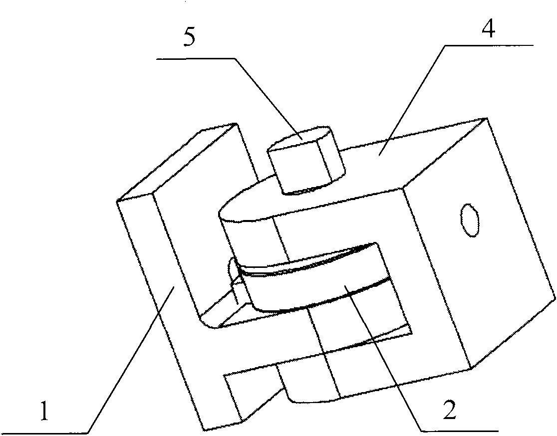
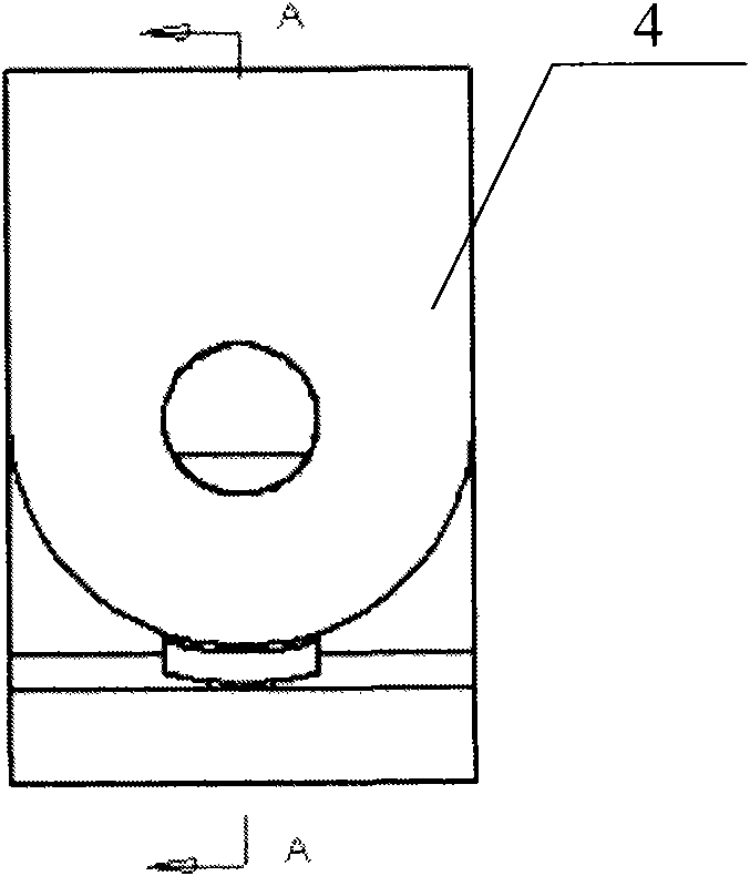
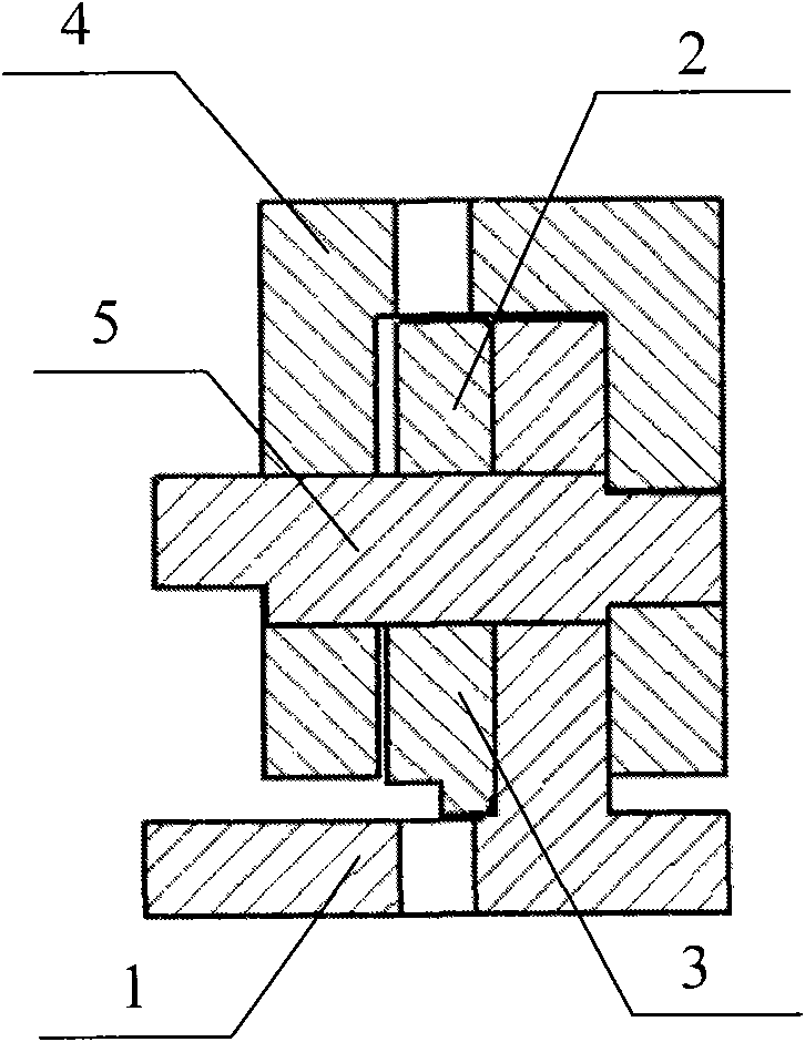
[0036] to combine Figure 1-Figure 8 , The main components of the assembled universal robot joint of the present invention include the articular process 1, the pulley piece 2, the locking pin 3, the glenoid socket 4 and the rotating shaft 5. If the processing is convenient, the pulley piece and the articular process can be combined into one part for processing, making it a whole. Due to the adoption of the assembly structure idea, each part cooperates with each other to limit the position, and no screws are needed. Each of the parts can be processed by light alloy, plastic or steel, such as the shaft), the locking pin 3 can be made of hardened steel, and the rest of the parts can be made of YL7075; the shape and size are determined by the needs of the use; the angle sensor can be a potentiometer Type angle sensors, such as RDC506 or PVS01, etc., can also use oth...


PUM


Abstract

The invention provides a split amounting type universal robot rotary joint and a spilt amounting method thereof. The rotary joint comprises an articular process, a pulley plate, a locking pin, an articular pan and a rotating shaft, wherein the pulley plate is provided with a gap; the shape of the locking pin is matched with the shape of the gap on the pulley plate; the pulley plate and the articular pan are connected into one whole body; the locking pin is embedded into the gap of the pulley plate; the articular process is embedded into the articular pan; holes of the articular process, the pulley plate and the articular pan are coaxial and the rotating shaft passes through the holes and is clamped by the locking pin. The invention adopts the idea of split-amounting type structure, has simple and compact structure, high reliability, no screw, can be dismantled by hands, is convenient to use and maintain on site; the invention can be suitable for joints of hands of the robot, in particular to the joints of skilful hands and the robot with size restriction, various low load rotating mechanisms without needing revolution, angle follow-up servo systems, rotating mechanisms which need to be controlled by tendons in a transmission way, rotating parts in toys, and other rotating devices with small rotating strength.

Description

(1) Technical field [0001] The invention relates to a joint mechanism for a robot. The invention also relates to a method for assembling a joint of a robot. (2) Background technology [0002] The quality of robot mechanism design often determines the quality of the overall performance of the robot. In the past, the mechanism of the robot was often specially designed for a specific function by adopting a specific transmission mode, installing a specific sensor, and implementing a specific function. In robotic mechanisms, rotation is the main motion form of joints, but there are few rotary joints designed for general purposes and high reliability requirements. In addition, the revolving joints of traditional robots are large in size, complex in structure, and difficult to disassemble and maintain. There is a lack of general-purpose, small-sized rotary joints, especially suitable for small bionic robots. [0003] In the transmission mode, the transmission mode of the robot ...

Claims


Application Information

Patent Timeline
IPC IPC(8): B25J17/00
Inventor 任化龙卢逢春边信黔
Owner HARBIN ENG UNIV
Learn More