Bidirectional compression type shoe gap adjuster

A brake shoe clearance and compression type technology is applied in the field of two-way compression brake shoe gap adjusters, which can solve the problems of complex structure, poor safety and reliability, and low adjustment accuracy of the adjuster, and achieve safe and reliable vehicle operation and easy processing. And the effect of reasonable assembly and design space

Inactive Publication Date: 2010-01-20
CRRC YANGTZE CO LTD +1
View PDF0 Cites 6 Cited by
  • Summary
  • Abstract
  • Description
  • Claims
  • Application Information

AI Technical Summary

Problems solved by technology

Its existing defects mainly include the following aspects: First, the structure of the adjuster is relatively complicated. In order to realize its telescopic action, four springs need to be used, and the difficulty of the assembly process increases correspondingly, and the manufacturing cost also increases accordingly; the second is that the adjuster The maximum shortening amount at one time is about 60mm, and the maximum elongation amount at one time is about 30mm. For the adjustment amount with a larger brake shoe clearance, it cannot be adjusted in place at one time, and it needs multiple adjustments to achieve it.
In this way, not only the adjustment method of the brake shoe clearance is complex and changeable, the efficiency is low, but also the adjustment accuracy is low, the error is large, and the clearance is not easy to control, which makes it difficult to maintain the brake cylinder piston stroke within the normal and constant range, acting on the wheel. The braking force becomes uneven, and the safety and reliability of vehicle operation deteriorates; the third is that the adjuster is only suitable for installation on the vehicle body, which limits the design space of the vehicle to a certain extent

Method used


Image

  • Bidirectional compression type shoe gap adjuster
  • Bidirectional compression type shoe gap adjuster
  • Bidirectional compression type shoe gap adjuster

Examples


Embodiment Construction

[0024] The two-way compression brake shoe clearance adjuster of the present invention will be described in further detail below in conjunction with the accompanying drawings and specific embodiments:

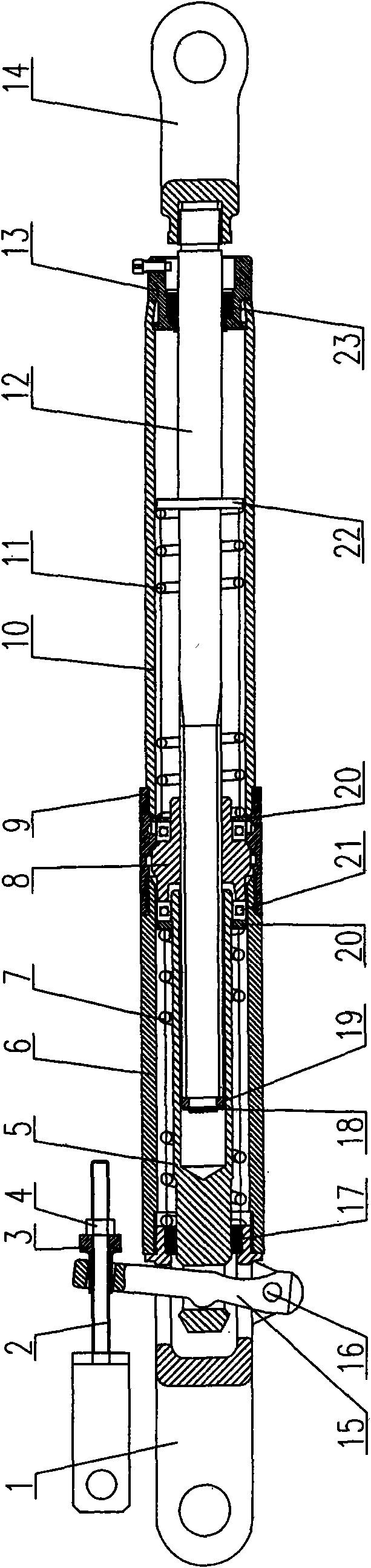
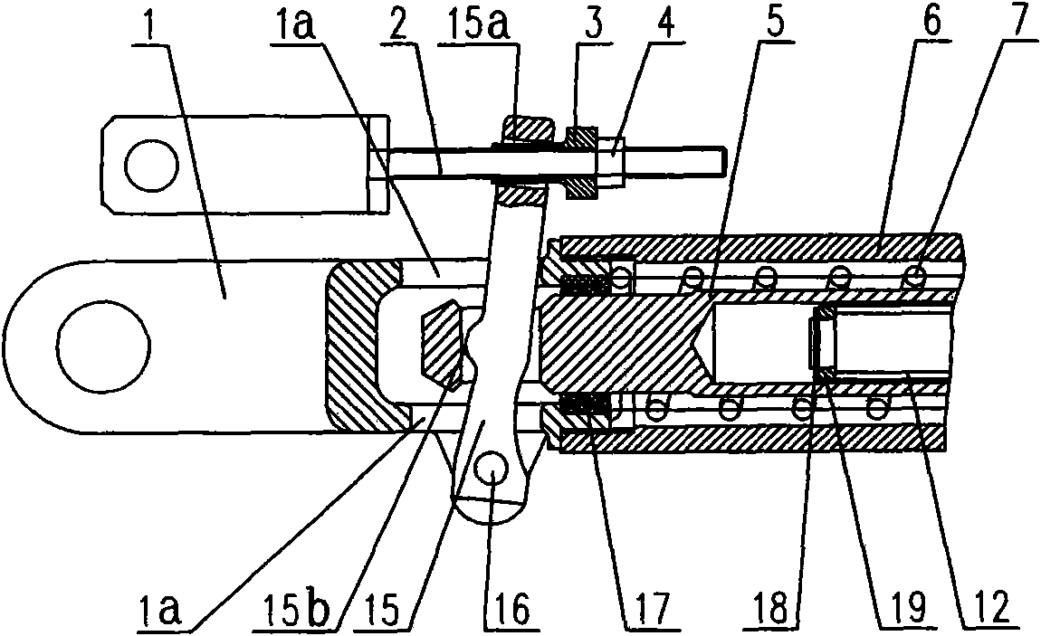
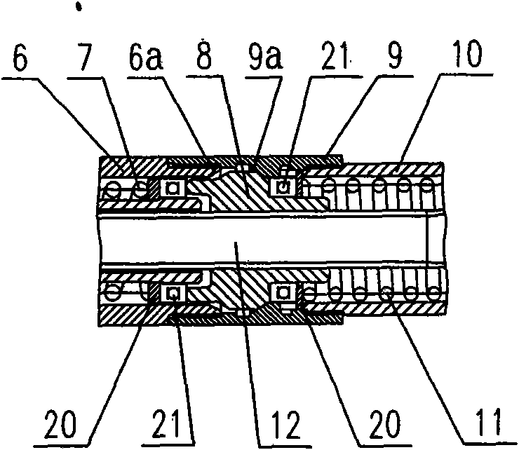
[0025] The two-way compression brake shoe clearance adjuster shown in the figure mainly consists of a first cylinder body 6, a second cylinder body 9, a third cylinder body 10, a first spring 7, a second spring 11, a coupling head 1, a control rod 2. It is composed of joystick 15, pull rod 5, adjustment nut 8, screw rod 12, hollow end cover 13 and other components. The structural relationship between the components is described in detail as follows:

[0026] A. One end of the first cylinder 6 is threadedly connected to the tail of the coupling head 1, the other end of the first cylinder 6 is threaded to one end of the second cylinder 9, and the other end of the second cylinder 9 is connected to the third One end of the cylinder body 10 is screwed, and the other end of the third...


PUM


Abstract

The invention discloses a bidirectional compression type shoe gap adjuster, comprising a coupling head, a first cylinder, a second cylinder, a third cylinder and a hollow end cover which are connected in sequence; an adjusting nut is arranged inside the second cylinder, and a pull rod is arranged inside the first cylinder; a screw rod penetrates through the first cylinder, the second cylinder and the third cylinder; a first spring is sheathed on the pull rod, and a second spring is sheathed on the screw rod; one end of a operating lever is hinged on the coupling head, the lever body thereof penetrates through a lateral through hole of the coupling head and a transverse through hole of the pull rod simultaneously, and the other end of the operating lever is connected with a control lever through a control lever mounting hole. Besides, the control lever is used for adjusting the magnitude of force applied by first spring and the second spring on the adjusting nut; acted by the bidirectional force applied by the two springs, the adjusting nut moves between the first cylinder and the second cylinder and engages with or disengages from the two springs. The bidirectional compression type shoe gap adjuster is suitable for rail wagon brake devices, has a simple structure, and can adjust shoe gap automatically and precisely so as to provide even brake force for rail vehicles.

Description

technical field [0001] The invention relates to a brake shoe gap adjuster in a railway wagon brake device, in particular to a two-way compression brake shoe gap adjuster. Background technique [0002] With the rapid development of railway transportation, the requirements for the braking devices of railway wagons are also getting higher and higher. The brake cylinder is one of the key components of the brake device, and its performance has a great influence on the reliability and service life of the entire brake device. For a vehicle with an excessively long piston stroke in the brake cylinder, its braking force will be reduced, and at the same time, the braking will lag behind that of other vehicles with normal piston strokes. For vehicles with too short piston strokes in the brake cylinder, the braking force will be increased, and the braking will be advanced compared to other vehicles with normal piston strokes. Regardless of braking lag or braking advance, the longitudi...

Claims


Application Information

Patent Timeline
Patent Type & Authority Applications(China)
IPC IPC(8): B61H15/00F16D65/56
Inventor 刘桂军涂智文易立东崔红王高方志坚马驰易新炳
Owner CRRC YANGTZE CO LTD
Why Eureka
Try Eureka