Combined type anchor padding plate and method for manufacturing same

A manufacturing method and anchor pad technology are applied in the field of pressure-bearing plates, which can solve the problems of high consumption of steel materials and high production costs, and achieve the effects of improving safety, low cost and uniform distribution.

Active Publication Date: 2010-01-20
LIUZHOU OVM MASCH CO LTD
View PDF0 Cites 11 Cited by
  • Summary
  • Abstract
  • Description
  • Claims
  • Application Information

AI Technical Summary

Problems solved by technology

[0004] The purpose of the present invention is to provide a composite anchor backing plate with optimized product structure, less consumption of steel materials, low cost, smaller stress under anchorage, and more uniform distribution, so as to solve the problem that the existing anchor backing plate consumes more ste

Method used


Image

  • Combined type anchor padding plate and method for manufacturing same
  • Combined type anchor padding plate and method for manufacturing same
  • Combined type anchor padding plate and method for manufacturing same

Examples


Embodiment 1

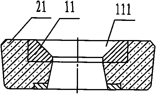
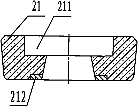
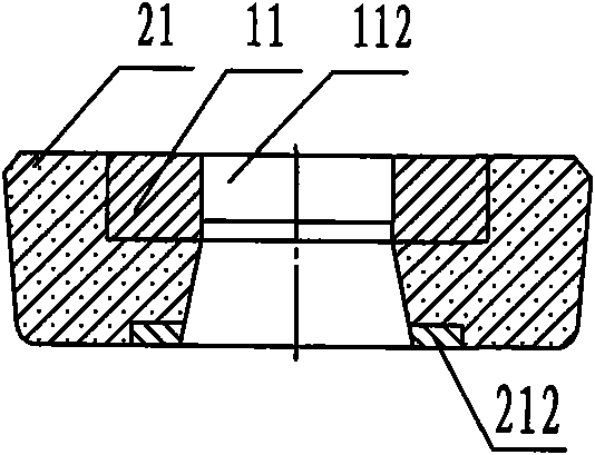
[0067] A composite anchor plate, such as Figure 1 ~ Figure 3 Shown: the profile of this anchor backing plate is a disc shape, and the middle steel backing plate is a flat cylindrical middle steel backing plate 11 (see figure 1 , image 3 ), and what is coated on the outer periphery of the flat cylindrical middle steel backing plate 11 is a disc-shaped ultra-high-strength concrete pressure-bearing member 21 with a stepped through hole 211 in it (see figure 2 ), the flat cylindrical steel backing plate 11 is placed on the step of the stepped through-hole 211 of the disc-shaped ultra-high-strength concrete pressure-bearing member 21 and is combined with it, and the other step of the stepped-shaped through-hole of the ultra-high-strength concrete pressure-bearing member 21 One end is trumpet-shaped, and there is a ring-shaped steel connecting plate 212 in the center of the bottom.

Embodiment 2

[0069] A composite anchor plate, such as Figure 4 ~ Figure 5 As shown: the shape of the anchor backing plate is a hollow disc-shaped structure, the middle steel backing plate is a disc-shaped hollow cast iron or steel casting 12 with grouting holes 122, and the outer circumference is tightly wrapped in the middle The outer edge of the steel backing plate and the approximately disk-shaped ultra-high-strength concrete pressure bearing parts 22, 121 are shallow grooves on the middle steel backing plate.

Embodiment 3

[0071] A composite anchor plate, such as Figure 6 ~ Figure 7 As shown: the shape of the anchor backing plate is a hollow structure approximately disc-shaped, and the middle steel backing plate is a thin circular middle steel backing plate 13 with a shallow groove; Ultra-high-strength concrete pressure-bearing part 23, the upper center of this approximately disk-shaped super-high-strength concrete pressure-bearing part 23 has a groove 231, and there is a grouting channel 241 formed by an iron bend on the disc (see Figure 6 ), the upper part of the iron elbow 242 is connected with the middle steel backing plate 13, and the lower transverse opening is connected with the central hole 232 of the ultra-high-strength mortar concrete pressure bearing part 23, and the oblate steel backing plate 13 is placed in the ultra-high-strength concrete pressure-bearing On the groove 231 of part 23 top center, and be connected with high-strength mortar concrete pressure bearing part 23, there i...


PUM

PropertyMeasurementUnit
Flexural strengthaaaaaaaaaa
Compressive strengthaaaaaaaaaa
Granularityaaaaaaaaaa

Abstract

The invention provides a combined type anchor padding plate, which is formed by a middle steel padding plate with a hollow central part and a super high strength concrete pressure-bearing piece coated on the lower part and/or the periphery of the middle steel padding plate; and the super high strength concrete pressure-bearing piece is a super high strength active powder concrete component of which the ultimate compressive strength is more than 120MPa and the ultimate breaking strength is more than 12MPa. The method for manufacturing the combined type anchor padding plate comprises the following steps: putting the manufactured middle steel padding plate used as an inner mould in a component forming mould for manufacturing the super high strength concrete pressure-bearing piece, adding the super high strength active powder concrete, manufacturing a moulding piece of the combined type anchor padding plate, which combines the middle steel padding plate and the super high strength concrete pressure-bearing piece, and performing working procedures of the moulding piece, such as natural curing and the like to manufacture the combined type anchor padding plate. The combined type anchor padding plate has the advantages of optimized structure, low steel consumption, low cost, smaller stress under the anchor, more uniform distribution of the stress under the anchor, more convenient dense casting of concrete under the anchor and more convenient field construction and laying of auxiliary reinforcements.

Description

Technical field: [0001] The invention relates to a pressure-bearing plate in a concrete building structure whose compressive strength value is more than three times lower than that of steel parts, which can reliably transfer and disperse high concentrated stress, especially a kind of anchorage An anchor backing plate for transmitting and dispersing concentrated force into a concrete anchorage area and a manufacturing method thereof. Background technique: [0002] Anchors for concrete structures are composed of anchors, anchor pads and reinforced steel bars. The anchors 4 anchor the prestressed tendons 3, while the anchor pads 8 and reinforced spiral steel bars 6 are pre-embedded in the concrete 7 (see Figure 9 , the clip 41 and the anchor plate 42 form the clip-type anchor 4 in the figure, and the anchor can also be other types of anchors) to disperse the concentrated stress transmitted by the anchor so that it can be more evenly transmitted to the Concrete to go. Since th...

Claims


Application Information

Patent Timeline
IPC IPC(8): E04C5/12C04B28/04C04B14/04
Inventor 朱万旭周红梅付委谭柳芳
Owner LIUZHOU OVM MASCH CO LTD
Why Eureka
Try Eureka